15 September, 2004
Installing an Auxiliary Fuse Panel
In planning upgrades to my MR2, I realized that many of them would include tapping into the electrical system for power. The SPAL fans, for example, are high-current items, and I was interested in a clean installation. With that in mind, I went looking for an auxiliary fuse panel to power any accessories I would be installing.
I found what I wanted in the Cirkit Boss (Part No. 70207) from Painless Wiring (www.painlesswiring.com). It's small, weatherproof, and has both switched and unswitched circuits. All fuses and a circuit breaker are included.
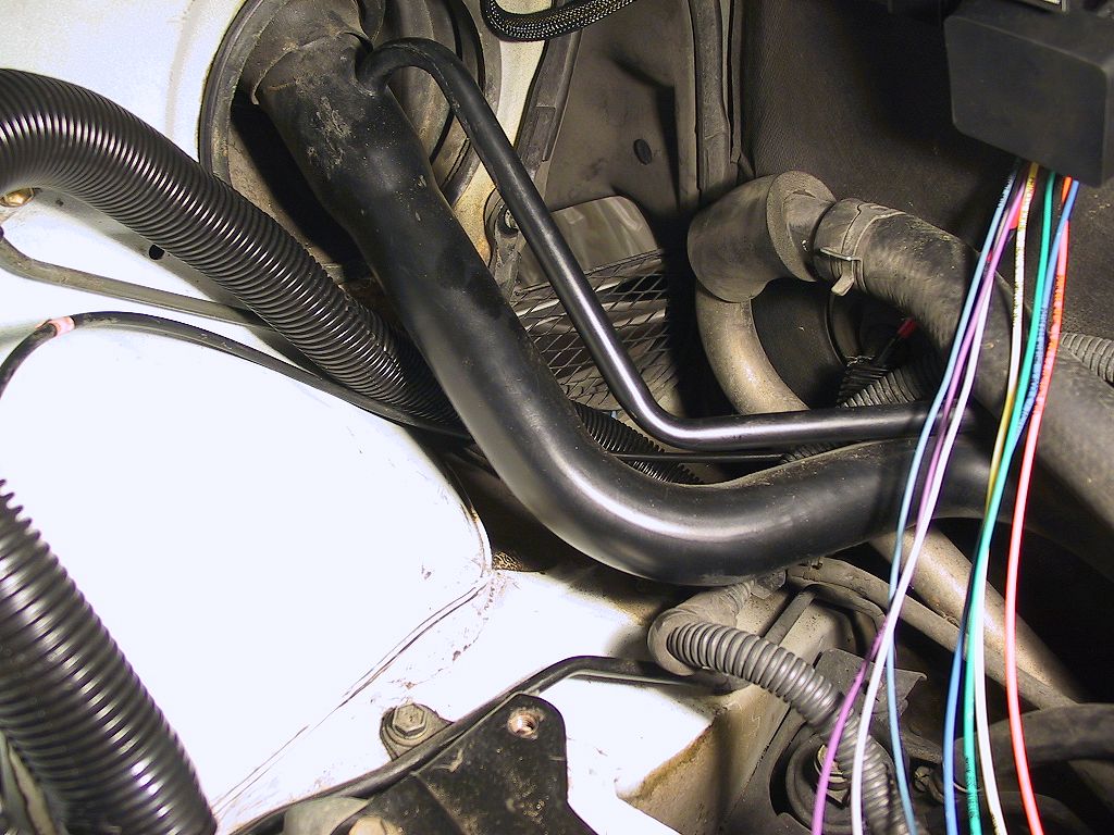
Space is at a premium in the engine bay, but I found plenty of extra nooks and crannies after replacing the stock air filter and airbox with an APEXi Power Intake.
Finally, remember that this is only a guide -- not gospel. What you do to YOUR vehicle is YOUR responsibility. I do not endorse, approve, authorize, or otherwise encourage you to make alterations to your vehicle. Be careful, and recognize the dangers associated with modifications to your vehicle's critical systems, like electrical, engine, brakes, etc.
Please contact me if you have comments or suggestions about the article or the project, or if you find errors on these pages.
Tools
Needed
-
10mm, 12mm, 13mm sockets and wrenches
-
Philips screwdriver
-
Drill, 1/8" drill bit,
-
Four (4) #10 x 1" Philips-head sheet metal screws with washers
-
Pliers (regular and/or needle nose)
-
Soldering iron & solder
-
Electrical tape
-
Polyethylene cable sleeving (optional)
-
Double-faced tape
-
Sharp knife (an X-acto would be fine)
Doing It
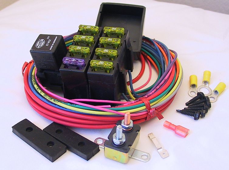
I liked this kit. They even print the circuit number on the wire (and whether it's switched or unswitched), so you don't need to keep consulting the (admittedly simple) instructions.
It wasn't cheap (about $70 from Summit Racing), but I think I'll
appreciate it in the long run. It's designed to protect your stock
electrical components from ill-behaved accessories, and that's what I was
looking for.
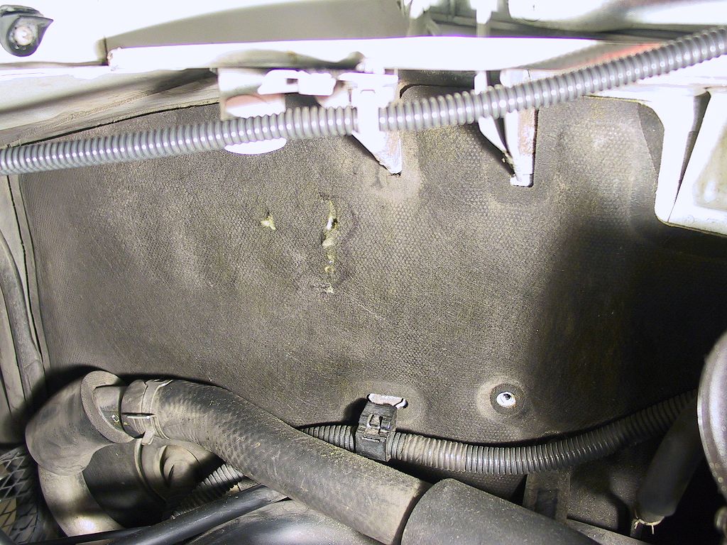
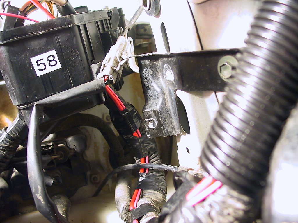
As you can see, I've already identified the area where I'm going to mount the fuse panel. This will be somewhat accessible, yet still leave room for some other devices nearby.
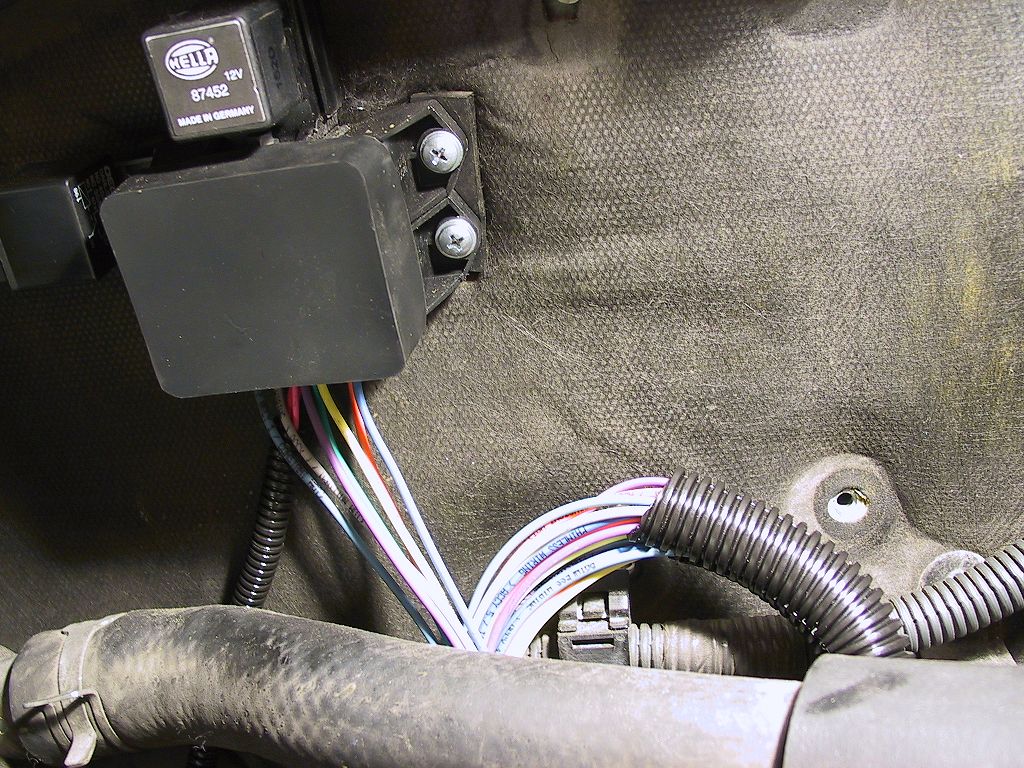
Instead of using the self-tapping screws included in the kit, I used four #10 x 1" Philips-head sheet metal screws with washers under the head. The thickness of the sound absorbing material on the bulkhead needs to be accounted for, and I preferred having a Philips head vs. a hex head.
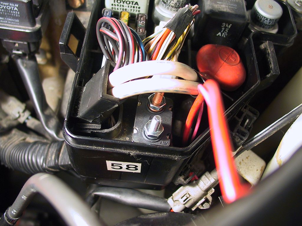
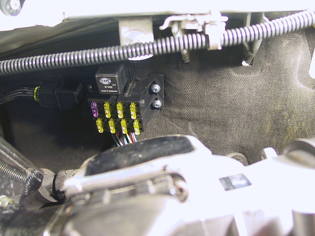
Here's a photo of the fuse block after mounting:

The black connector on the left side of the panel is a relay and socket
for the SPAL fans, when I get around to replacing the intercooler.
The kit includes a waterproof cap that fits over the fuses for protection
from the elements.
Afterward, I replace the sleeving with new sleeving. Here's the result:
You can see the rubber cap that fits over the fuses, and the short length of 1/4" sleeving on the leads to the main fuse panel.
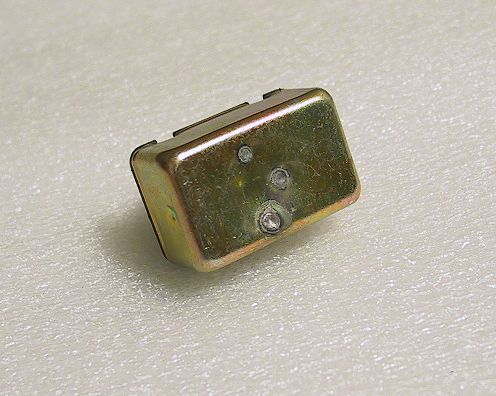
I used a piece of double-faced tape to keep the circuit breaker in place, although it will not be moving around once the wires are in place.
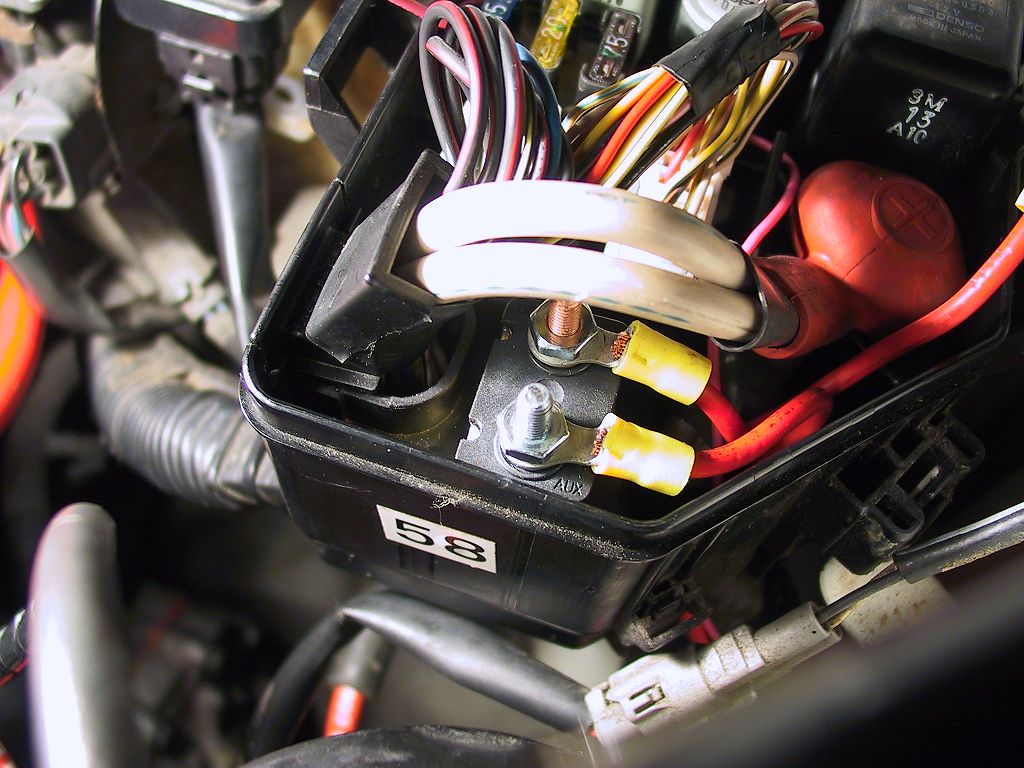
I crimped on a larger ring terminal to the other end connect to the main hot terminal:
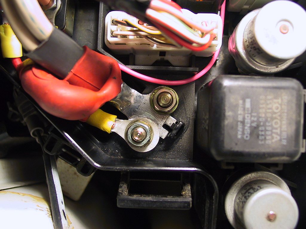
The red rubber boot fits nicely over the terminals.
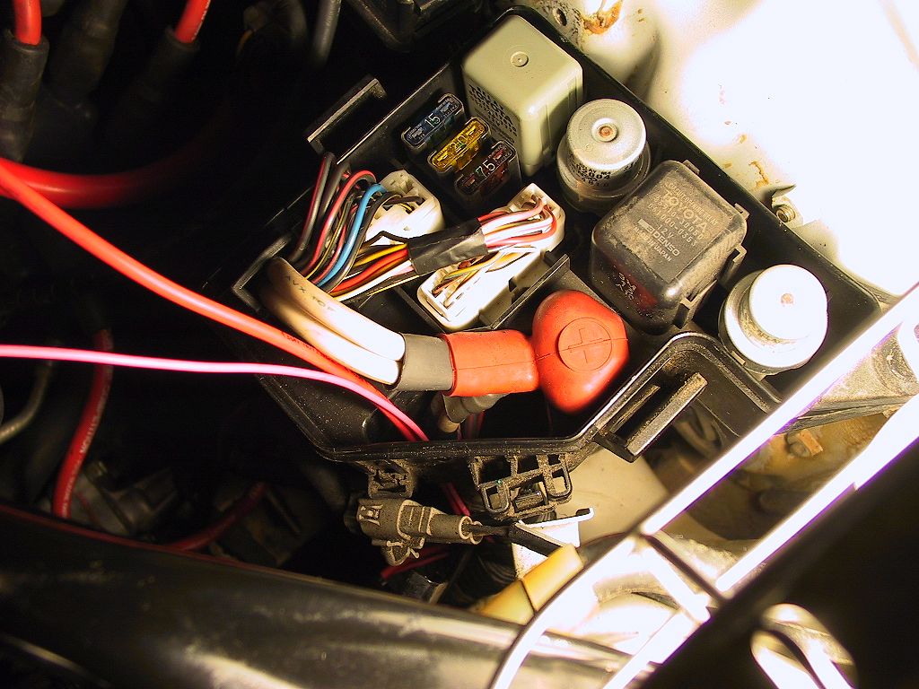
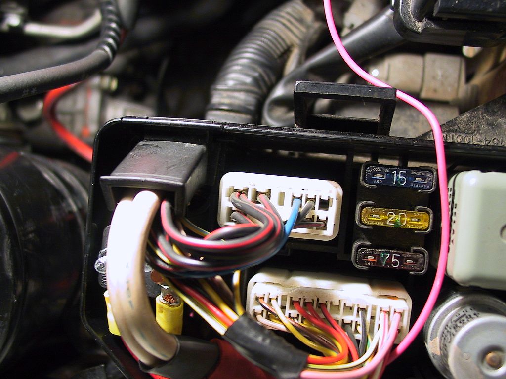
Looking down at the connector nearest the edge of the fuse box (at the
top of the photo), the black & red striped wires all are switched on
with the ignition. Since there is little load on this wire, you can choose
any of these:
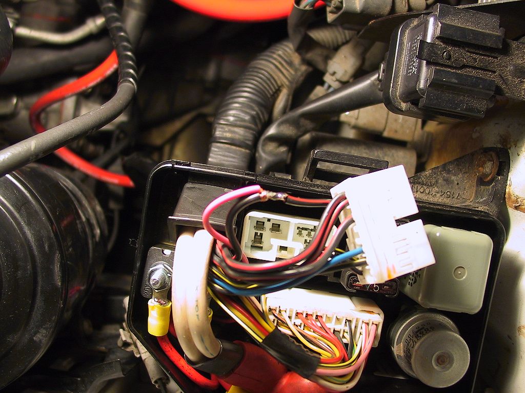
I carefully wrapped the splice with electrical tape, and reassembled the connector and closed up the main fuse panel.
The fuses are easily accessible with the Intake in place, although I will probably remove the intake when adding electrical connections to the panel.
1993 MR2 Turbo