|
Page  1
2
1
2
 |
|
|
Installing a
SPAL Intercooler Fan
(continued)
|
|
|
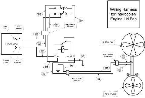
While the circuit diagram I drew up in Visio helped me
to visualize how the components worked, I need a wiring guide to keep
all the wires sorted out, to show where I would install the modular
connectors, etc. As you'll recall, I was doing this as part of a larger
project, and there were wires everywhere.
So, I took the circuit diagram and modified it to create a practical
wiring diagram. If you click the image below, you can get the full-size
PDF version of the drawing.
|
|
|
|
I removed the temperature sensor for the
stock IC fan, which is located in the engine lid:
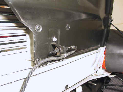
I just clipped the leads as close as possible where they entered the
wiring harness.
|
|
|
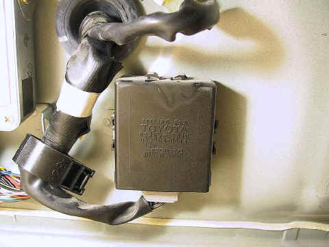
The stock fan circuit has its own ECU,
located in the rear luggage compartment, next to the main ECU:
|
|
|
I unplugged the wiring harness connector,
wrapped it in plastic, and zip-tied it to keep it protected:
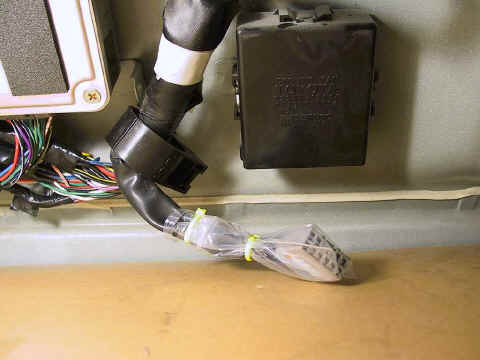
I then removed the ECU from its mounting.
|
|
|
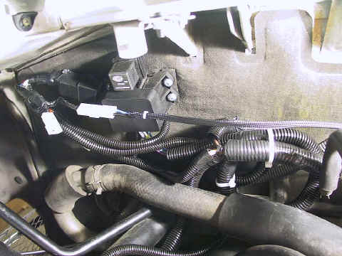
I attached the relay to one of the auxiliary
fuse panel's mounting screws, and wired the leads into fuse box two
circuits: one "hot" (ignition off) and one switched (ignition
on). Each circuit is rated at 20 amps.
I wrapped the leads for the fan in
some woven cable sleeving, then ran them across the engine compartment to
the fan:
|
|
|
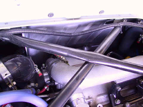
For added protection, I installed a section
of ribbed cable sleeving like the stock setup used:
|
|
|
The wiring for the switch had already been
routed through the tunnel to underneath the dash. I connected the wires
using female spade connectors which matched the male connectors on the
switch. I don't have a photo of the actual connections, but it's very
straightforward.
|
|
|
That's all there was to it. The fan works
exactly as I had planned, and adding the engine lid fan will simply be a
matter of connecting the fan's leads to the existing circuit.
|
|
|
|
|
|
Page  1
2
1
2
 |
|
|
|
|
|
Dave Martin
1993 MR2 Turbo
|
|
![]() 1
2
1
2
![]()

![]() 1
2
1
2
![]()