29 September, 2004
Page
![]() 1 2
1 2
![]()
Installing a
SPAL Intercooler Fan
When I installed my GReddy Intercooler, I also installed a SPAL 7-1/2" puller fan from ATS in place of the stock unit. I chose to remove the stock temperature sensor and use a manual switch to control the fan.
Since this unit was installed as part of a larger project (which included an APEXi AVC-R boost controller, GReddy Intercooler, GReddy Oil Catch Can), some of the photos might show more disassembly than is actually required. It's also likely that the photos don't always match EXACTLY what's in the text. As is often the case, I would have changed the sequence of a few things if I had to do it over again.
This article focuses on the electrical aspects of the fan installation. For details on the mounting of the fan, please see my GReddy Intercooler installation.
First, I need to thank Marc Summers for his contribution. Since I am generally inept around electronics once I get past "connect the red wire to the red terminal" phase, his contributions proved invaluable. He describes some of the important considerations in adding a high amp device to your wiring scheme. After several false starts, I was able to create a wiring plan that suited my needs.
Note that I also added an auxiliary fuse block. This is not necessary to add the fan, but I wanted to plan for any future electrical additions in advance. Simply use a fuse in place of the fuse panel connections for your installation.
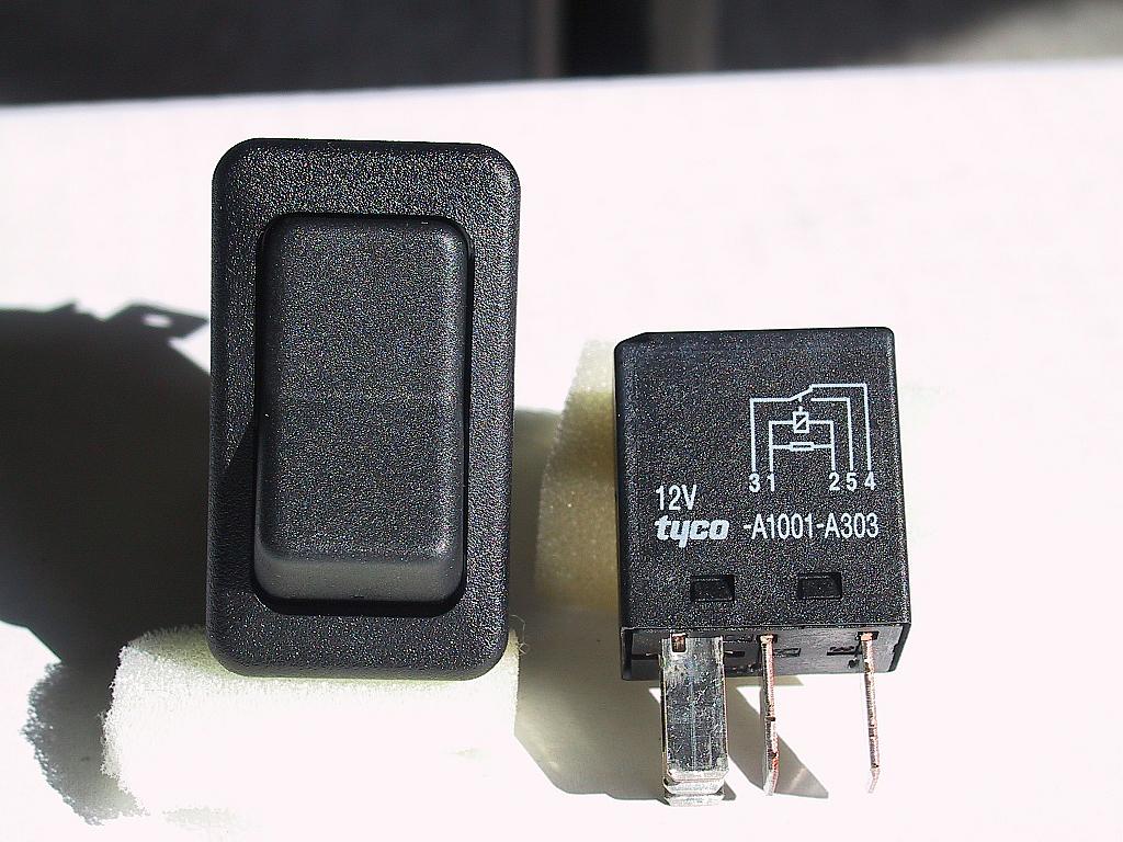
The fan is wired to a three-position rocker switch. The normal position is to have the fan come on with the ignition. The other options are OFF and ALWAYS ON. The ALWAYS ON position is useful to help cool down the engine so I can work on it, and (hopefully) to cool the IC between dyno runs. This switch scheme complicates the wiring a bit, but not overly so.
Finally, remember that this is only a guide -- not gospel. What you do to YOUR vehicle is YOUR responsibility. I do not endorse, approve, authorize, or otherwise encourage you to make alterations to your vehicle. Be careful, and recognize the dangers associated with modifications to your vehicle's critical systems, like electrical, engine, brakes, etc.
Please contact me if you have comments or suggestions about the article or the project, or if you find errors on these pages.
Tools/Materials Needed
-
30 amp automotive-type relay (Radio Shack #90-2394 or similar)
-
Optional relay socket (Radio Shack #90-2396 or similar)
-
10 �F non-polar electrolytic capacitor (Radio Shack #90-2099 or similar)
-
1-Amp 1000-PIV diode (Radio Shack #90-2955 or similar)
-
Four 10-foot lengths of various colored 18 AWG hookup wire
-
Two 5-foot lengths of various colored 14 AWG hookup wire
-
Cable sleeving (woven and convoluted) in a variety of sizes
-
DPDT Rocker switch (Eaton Euro SR #8006K40N1V2 or similar)
-
SPAL 7.5" puller fan
-
Cable ties
-
Soldering iron and rosin-core solder
-
Molex electrical connectors from McMaster-Carr (or similar). McMaster-Carr calls these "Miniature Pin-and-Socket Connectors"
-
Wire cutters, strippers, etc.
Doing It
In many ways, this was an intimidating project. While I'm not afraid to dive in and take an engine apart, once I get beyond simple electrical connections, I'm lost. Start talking about rectifiers, diodes, or transistors, and I'm nodding my head trying not to look totally inept.
Mark Summers has several instruction guides in the MR2 Archives, but there were no photos or diagrams of the electrical details. On the other hand, this was simply installing a switch and relay. Just a pesky capacitor and diode to overcome. Right.
In addition to the 7-1/2" fan on the intercooler, I hoped to add a 10" fan in the engine lid later. I decided to add the wiring for this fan to my circuit, and power it identically to the IC fan. I think a 30-amp relay will handle both, so adding the second fan is simply a matter of providing a second power stub.
I figured the best way to understand how the circuit should work would
be to design it on paper, then turn it into reality. Overkill, but
valuable as a learning tool.
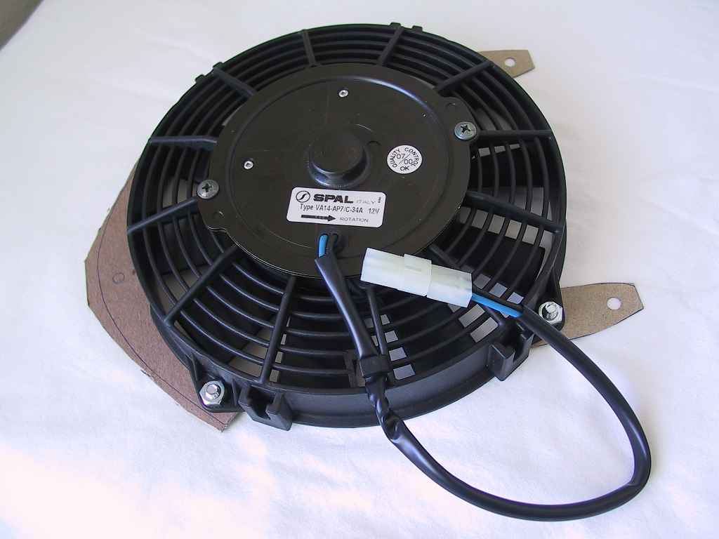
The SPAL "puller" fan is shown below. You can see the templates I used to fabricate mounting brackets. You can read more about these in my documentation of the intercooler installation.
I removed the stock electrical connector that was attached to the leads on the SPAL in favor of a Molex 2-circuit modular connector.
The switch is a perfect match for the knockouts on the MR2's dash, as shown here:
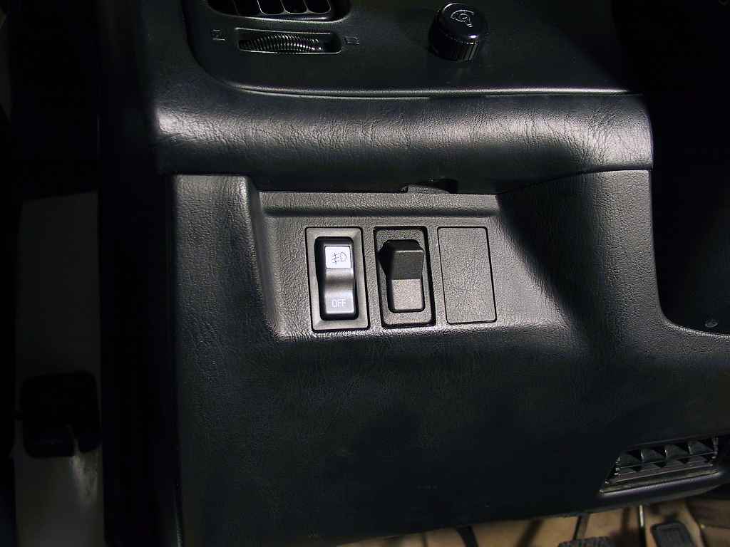
The switch looks more "stock" than the fog light switch next to it!
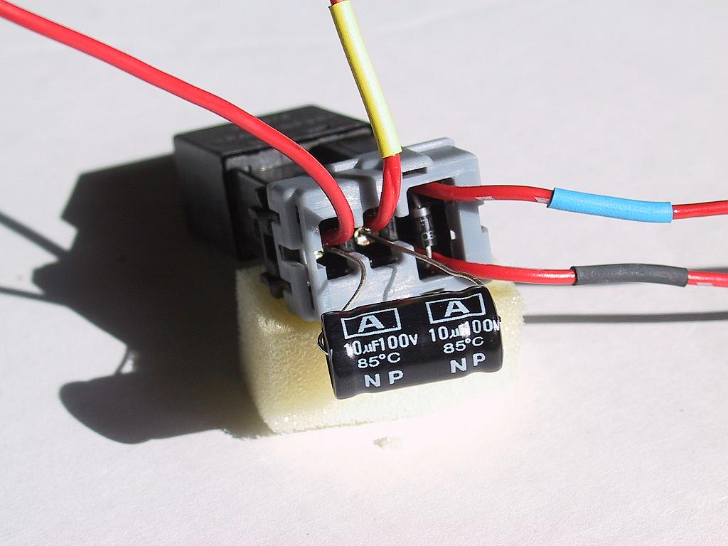
The heat-shrink bands are simply there to distinguish the leads from each other during assembly.
Page
![]() 1 2
1 2
![]()