GReddy Intercooler Installation
(continued)
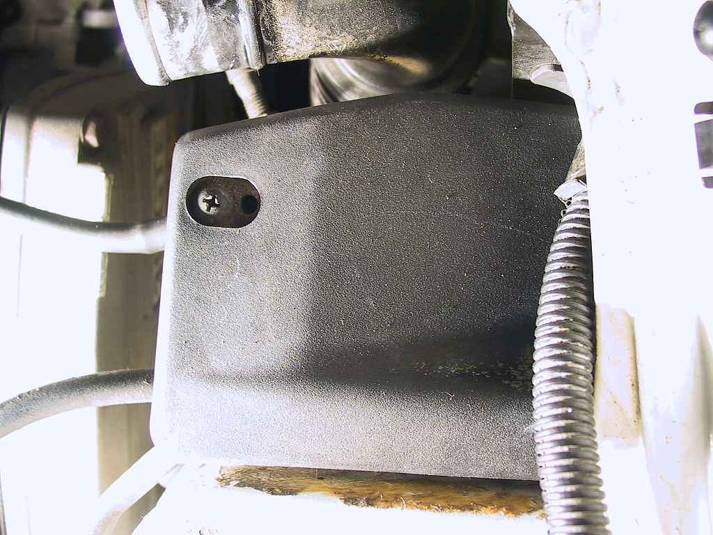

The cable from the throttle pedal is (naturally) the bottommost cable. It needs to be removed to get it out of the way.
I always choose to loosen the lock nut with the most available threads showing, and leave the other one in place. That lets me loosen the cable fully without needing to readjust the amount of slack later.
Once the cable is removed, you
can push it behind the turbo for now.

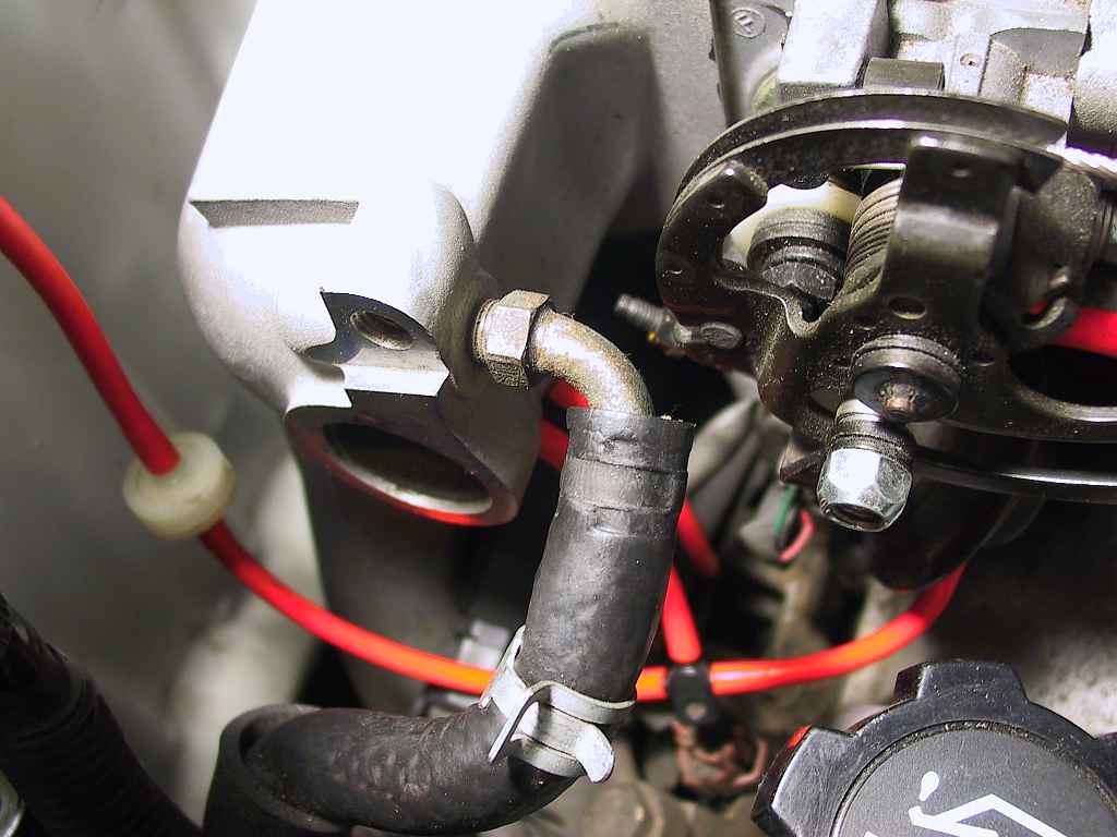
...and also at the intake manifold:
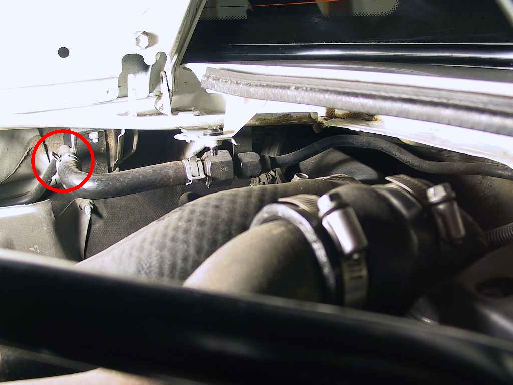
The line is clamped to the body with several 10mm nuts. Once they have been removed, you can set it aside. Make sure you cover the ends to prevent dirt from getting into the system, and tape over the exposed openings.
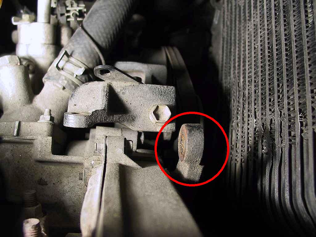
This bracket poses a danger to the IC core, so work around it carefully if you are trying to save the stock IC.
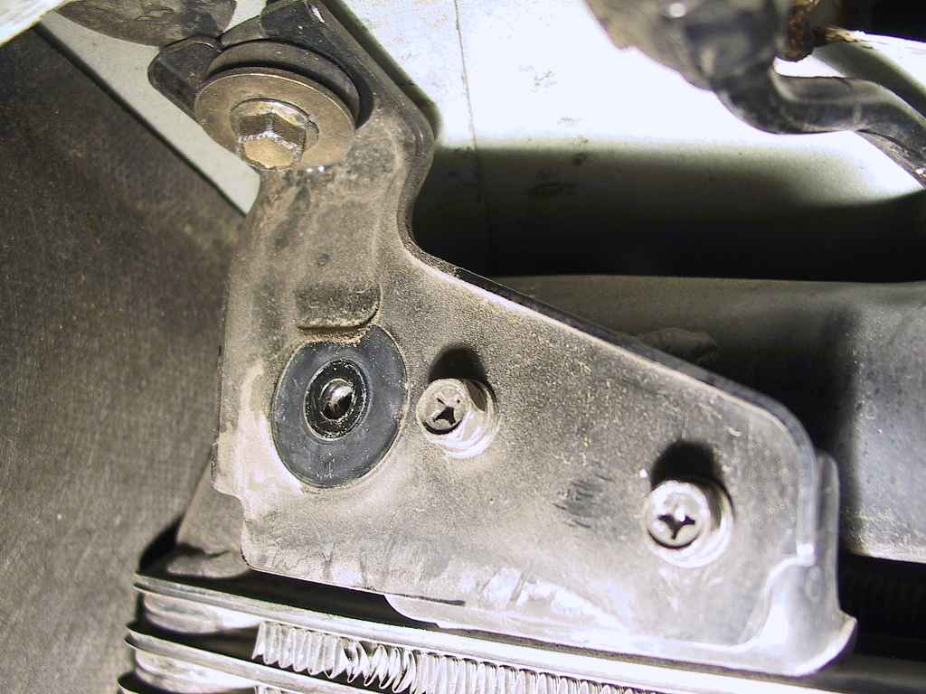
Now remove the two 10mm bolts that fasten the bracket to the intercooler.


Remove these, but be careful, as the IC might want to slip out of its saddle when the last one is removed.