10 October, 2004
Installing an APEXi AVC-R
Electronic Boost Controller
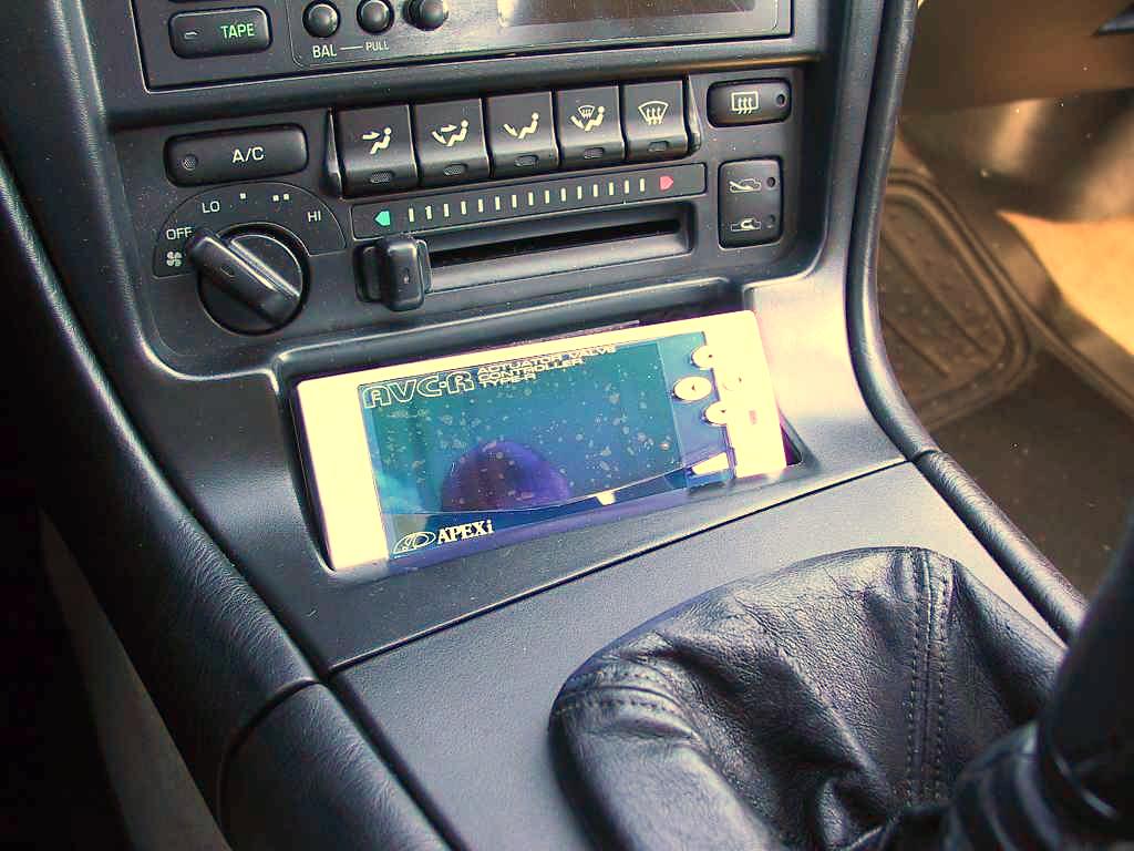
This unit was installed as part of a larger project which included a J&S Safeguard, GReddy Intercooler, SPAL IC fan, GReddy Oil Catch Can, and some gauges. Because of the scope of my project, some of the photos might show more disassembly than is actually required. It's also likely that the photos don't always match EXACTLY what's in the text. As is often the case, I would have changed the sequence of a few things if I had to do it over again.
Finally, remember that this is only a guide -- not gospel. What you do to YOUR vehicle is YOUR responsibility. I do not endorse, approve, authorize, or otherwise encourage you to make alterations to your vehicle. Be careful, and recognize the dangers associated with modifications to your vehicle's critical systems, like electrical, engine, brakes, etc.
Please contact me if you have comments or suggestions about the article or the project, or if you find errors on these pages.
Tools/Materials
Needed
-
Soldering iron & solder (low wattage)
-
Phillips and flat-bladed screwdrivers in various sizes
-
10mm and 12mm sockets with assorted extensions
-
Sharp Xacto knife or similar cutting tool
-
Wire cutter/stripper tool
-
Electrical tape
-
Assorted wire ties
-
Ribbed cable sleeving (Optional)
-
Braided cable sheathing (Optional)
-
3-10 feet of 22 AWG hookup wire in 6 different colors
Doing It
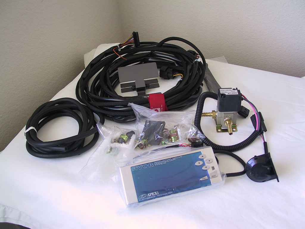
The kit includes many individual pieces designed to assist in the
installation, as shown here:
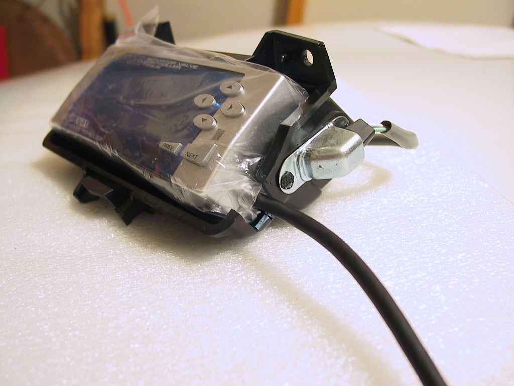
In this photo, I have already addressed the major shortcoming of the
kit, which is the inadequate length of the wire harness that leads to
the ECU. For my 93 MR2 Turbo, I extended this section about 10 feet,
then used a braided sleeving over the bundle. This harness section
contains six leads, so it helps if you can use colors that match the
original 22 AWG leads (Red, Purple, Green, Black, Gray, & White).
10 feet was more than I needed, but I figured it was
better to chop some wire off than be too short.
Although the ashtray lamp housing is still attached in this photo, I later removed it, as it was totally unnecessary.

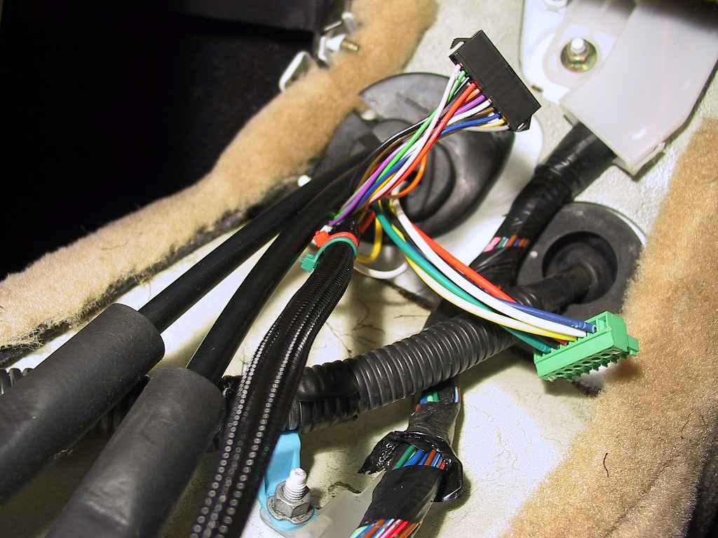
...and routed the cable along the right side of the console to the rear bulkhead.
Once the control module was ready, I turned to the other three components: the pressure sensor, the solenoid valve, and the ECU connections.
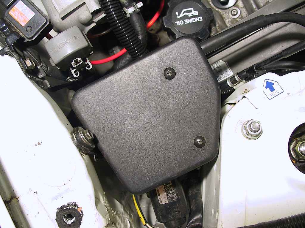
First remove the two screws, then remove the cover.
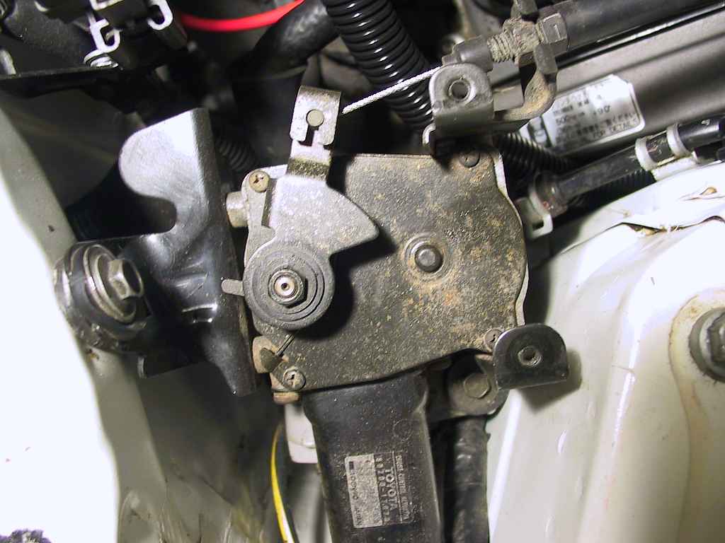
...and you can remove the unit.
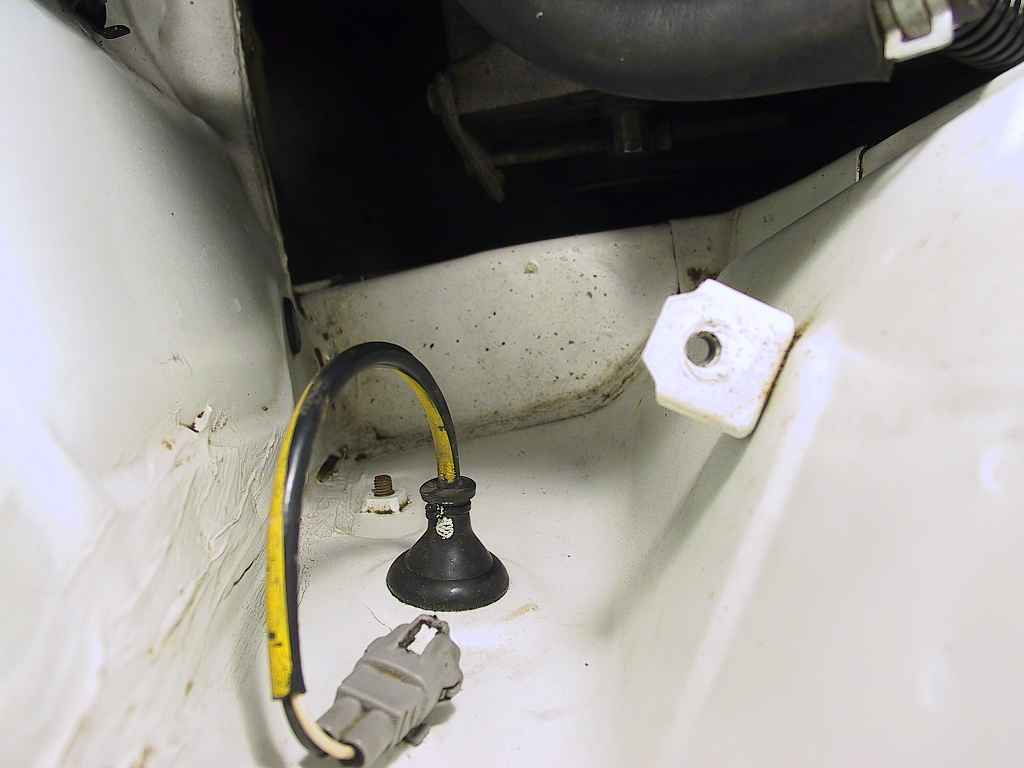
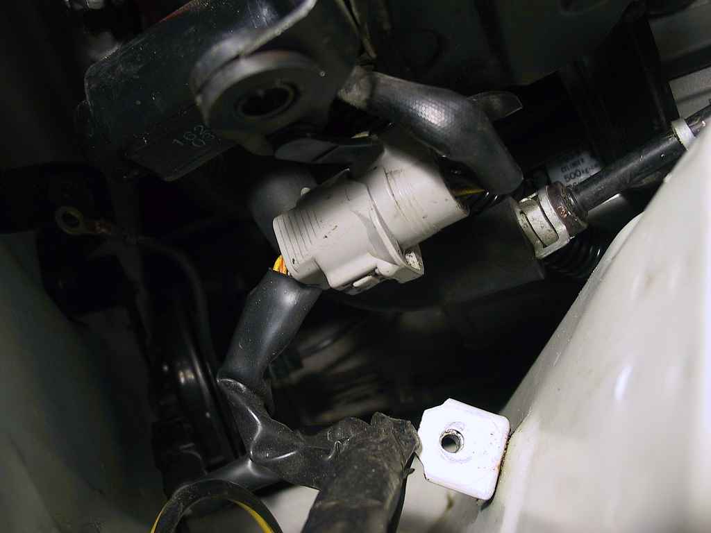
The white cylindrical object is a filter on the line leading to the stock boost gauge sensor. The vacuum line at the bottom of the photo leads to the APEXi pressure sensor, and it has its own inline filter.
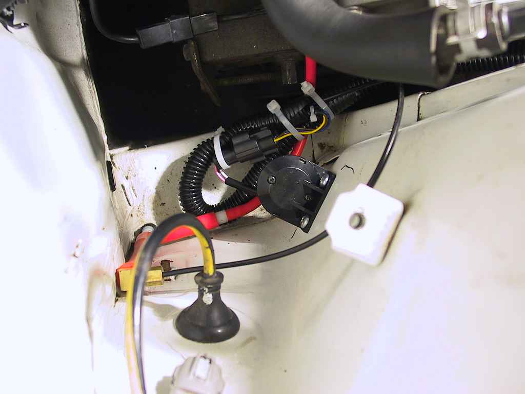
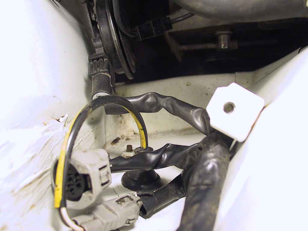
I installed another T-fitting on this line. One leg goes up to the APEXi pressure sensor through the supplied filter.
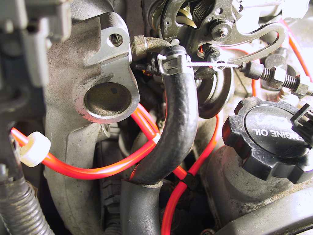
The other leg (leading away from pressure sensor) is connected to a brass compression fitting that changes the vacuum hose from silicone to 1/8" nylon tubing. The nylon tubing is much easier to run long distances and through tight spaces. This tube will be used for both the boost gauge I installed and the boost inlet on the J&S safeguard unit.