12 November, 2004
GReddy Intercooler Installation
I performed this installation as part of a larger project which included an
APEXi AVC-R boost controller, J&S
Safeguard, GReddy Oil Catch
Can, and some
gauges. I also installed a SPAL
7˝" puller fan as part of the IC upgrade. I can't imagine putting the
stock fan on a new intercooler, and I doubt anyone else would, either. I
installed a special circuit that would enable this fan to be energized either
with ignition power or battery power, or turned off entirely.
Because of the scope of my project, some of the photos might show more disassembly than is actually required. It's also likely that the photos don't always match EXACTLY what's in the text. As is often the case, I would have changed the sequence of a few things if I had to do it over again.
I've not listed the torque settings for the various fasteners. I consulted the BGB on most of them, but I've also learned that the BGB has errors, and some of them refer to incorrect torque settings. I'd like to avoid any potential for someone to point their finger at my instructions as the cause of that broken or lost fastener. If I find an incorrect setting that could cause a problem, I'll mention it, but generally you should use your own experience and the BGB as the guide. If you don't have the BGB, get a set.
The materials list is specific to my project. You will likely make some choices different from my own and your list will vary somewhat. I hope I have included most of the tools, etc., required, but my memory is not what it used to be.
While most of this work was performed by myself, I did solicit the help of a friend for removal of the stock intercooler. I was trying to remove it undamaged, and this proved close to impossible for one person without removing the right-hand motor mount. It might be possible, but I took the easier route.
The photos in this guide can be enlarged by clicking on them. This will greatly improve the clarity of the area in question.
As with most projects, many people deserve credit for providing ideas, plans, and materials. Here are a few of the direct contributors:
Marc Summers for the SPAL fan wiring ideas
Anthony Sarno for his intercooler installation write-up on MR2.com (www.mr2.com/article/greddyic_install.html)
Aaron Bunch for the SPAL fans (www.atsracing.net)
McMaster-Carr, which is an invaluable source of materials and hard-to-find items. They have an expansive selection of parts on their web site (www.mcmaster.com), they'll fill any size order, and they ship the same day 99% of the time.
Finally, remember that this is only a guide -- not gospel. What you do to YOUR vehicle is YOUR responsibility. I do not endorse, approve, authorize, or otherwise encourage you to make alterations to your vehicle. Be careful, and recognize the dangers associated with modifications to your vehicle's critical systems, like electrical, engine, brakes, etc.
Please contact
me if you have comments or suggestions about the article or the project, or
if you find errors on these pages.
Tools & Materials Needed
For disassembly and installation:
-
10, 11, 12, 13, & 14mm sockets in a variety of drive sizes.
-
A very healthy assortment of socket extensions and adapters. If you've done any work on an MR2, you know that you can never have too many different sizes of extensions.
-
10, 11, 12, 13, & 14mm combination wrenches
-
Assorted screwdrivers
-
Floor jack and jack stands
-
Optional T-Bolt hose clamps (McMaster-Carr)
For fabricating fan brackets:
-
Electric portable jig saw & electric drill (at a minimum)
-
Bench grinder
-
Bench vise
-
Bastard file and sandpaper
-
8mm cap screws in lengths of 25mm, 30mm, 40mm, & 50mm. Also needed are lock washers, flat washers, fenders washers and rubber washers. I used stainless steel fasteners where possible.
-
Aluminum sheet stock, approximately .100" thickness
For electrical devices:
-
30 amp automotive-type relay (Radio Shack #90-2394)
-
Optional relay socket (Radio Shack #90-2396)
-
Non-polar capacitor (Radio Shack #90-2099)
-
A 100V diode (Radio Shack #90-2955)
-
Four 10-foot lengths of various colored 18 AWG hookup wire
-
Two 5-foot lengths of various colored 14 AWG hookup wire
-
Cable sleeving (woven and convoluted) in a variety of sizes
-
DPDT Rocker switch
-
SPAL fans
-
Cable ties
Doing It
Here are the components that ship with the GReddy
Intercooler kit:

I was lucky enough to get some English-language instructions with the
kit, but overall the quality of the drawings is so poor that you are
pretty much on your own. I hope to provide some additional details with
the photos I took.
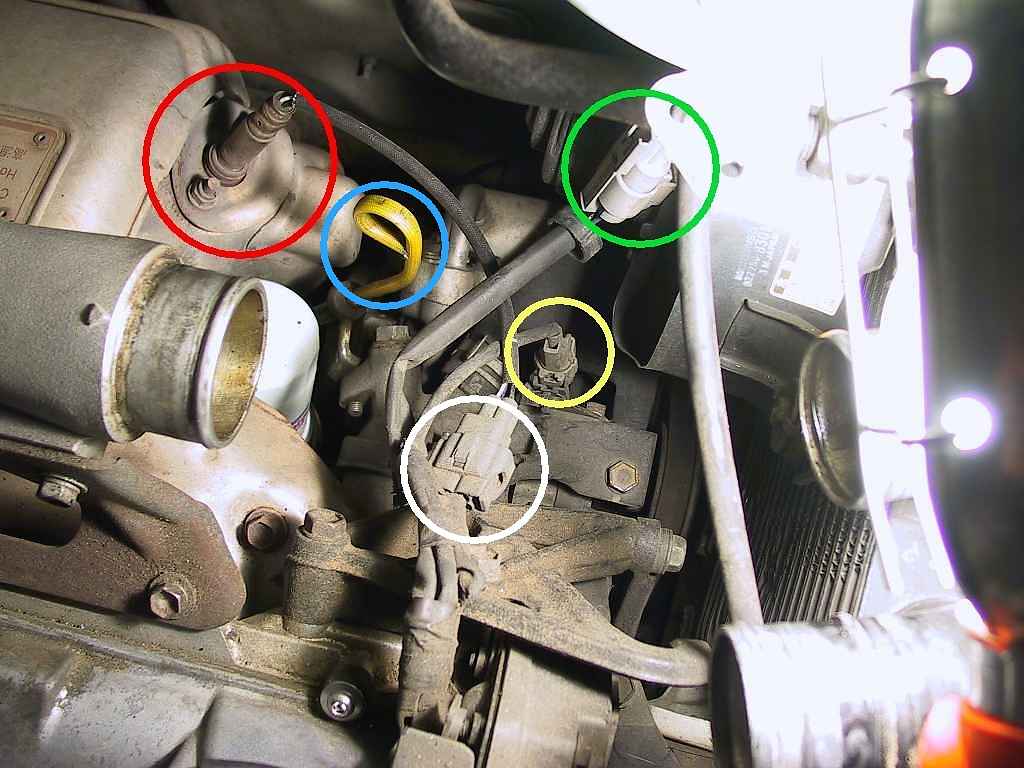
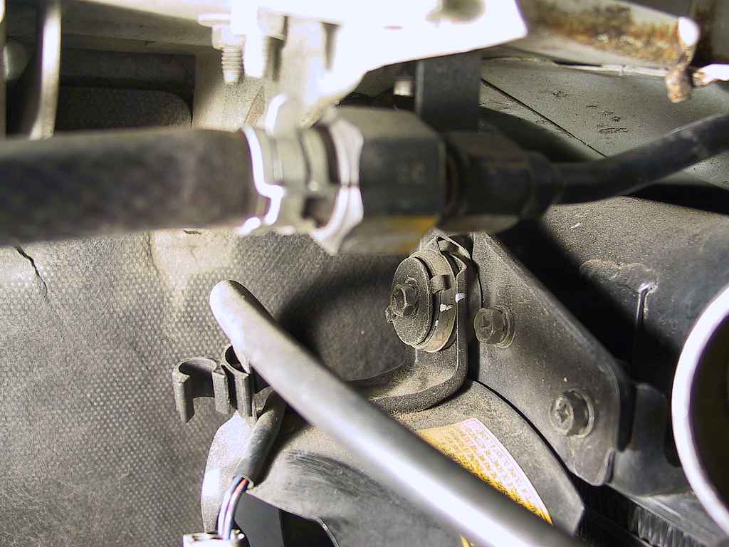
Now is also the best time to disconnect the oxygen sensor (circled in red above), its electrical connector (circled in white), the intercooler fan connector (circled in green), the A/C clutch connector (circled in yellow), and the dipstick (circled in blue). If you are going to use a new circuit for the fan, this is a good time to clip off the fan connector as well.
Make sure to tape over the openings for the oxygen sensor and dipstick
tube.
I'm not certain if this is required, but it's quick and easy and gives you more room to work. It also avoids the temptation to brace yourself on the intake pipe, which wouldn't hold the weight.
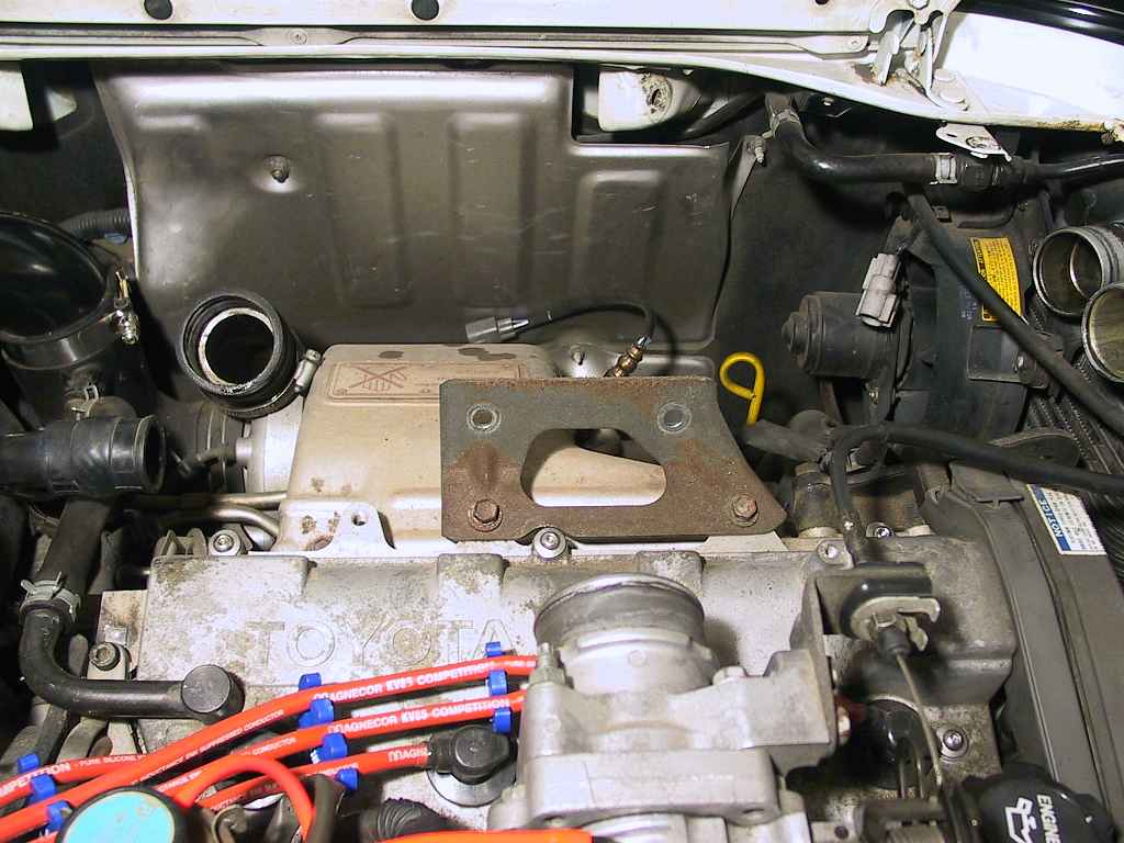
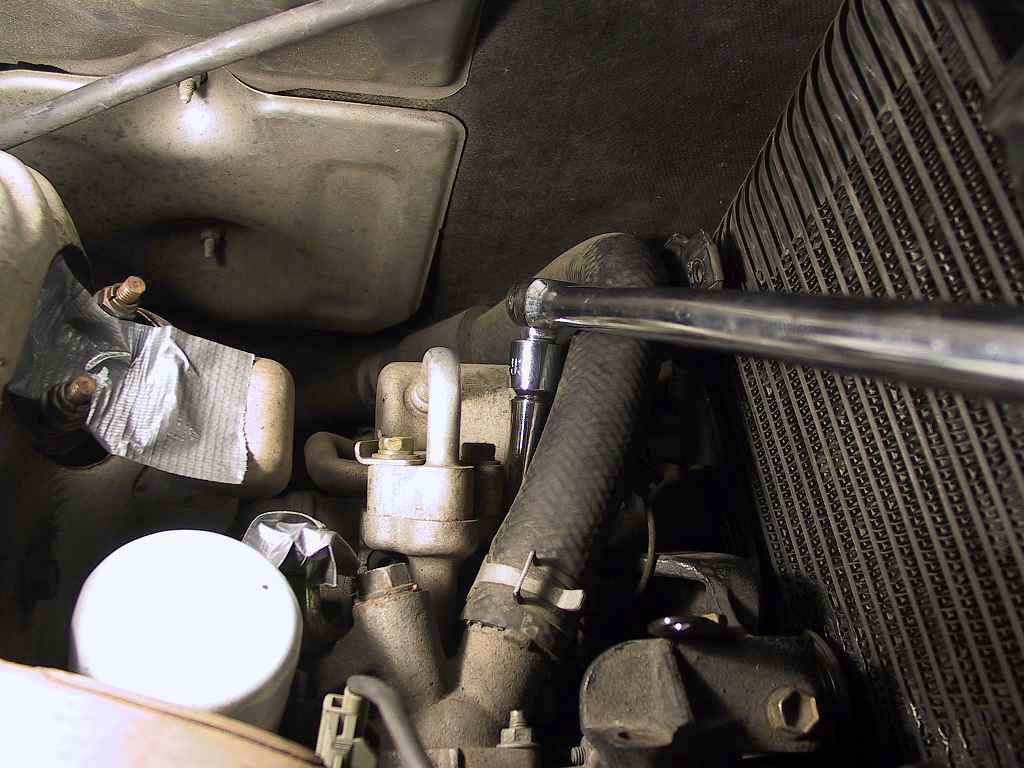
I took care to cover all open pipes with duct tape to prevent anything
from falling into the openings.
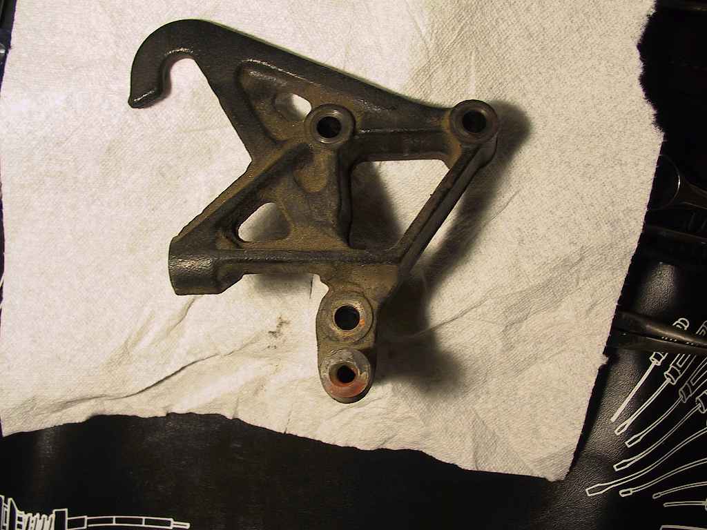
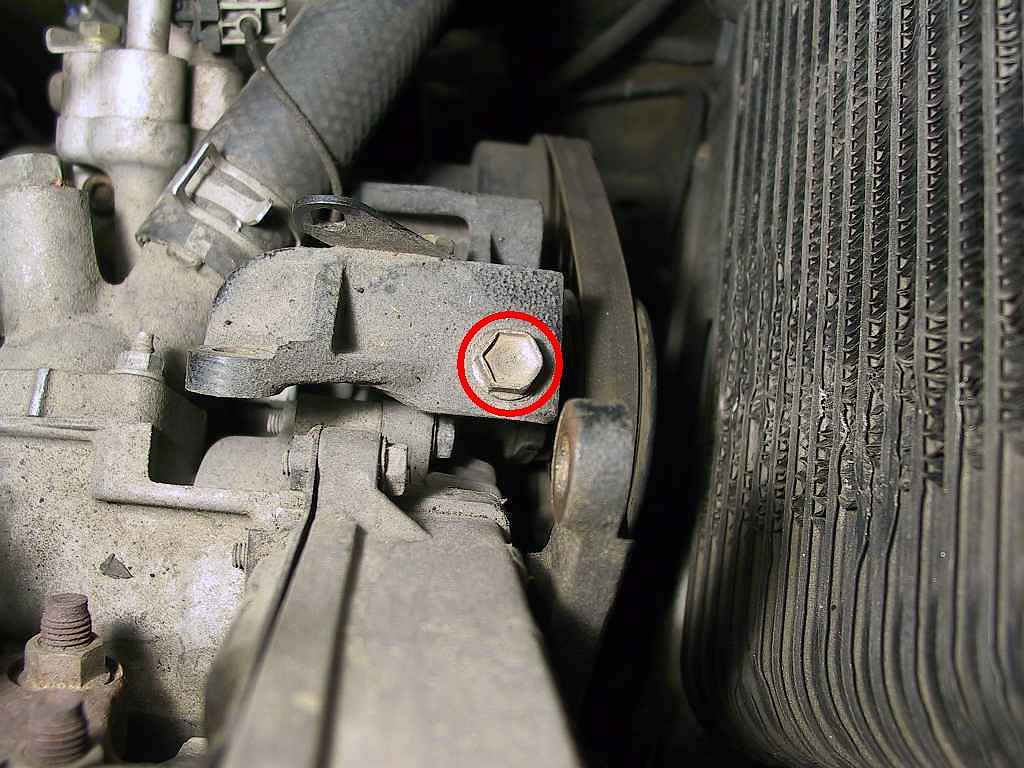
Seeing the bracket like this makes it a bit easier to locate the bolts when it's still mounted on the engine. Here's an in-place photo from above:
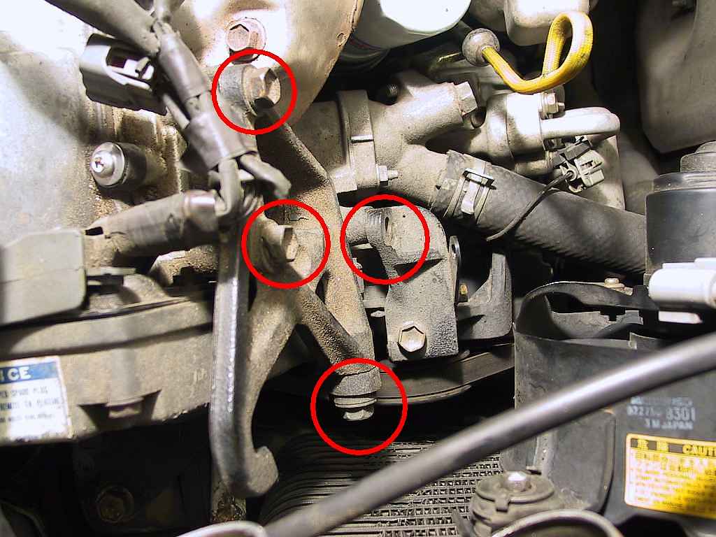
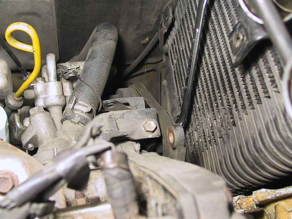
There should be four 14mm bolts to remove, although as you can see in this photo one of them is missing. Two of the bolts secure the bracket to the engine, while the other two are used to secure the A/C idler pulley bracket to the hanger bracket. Remove all four and you can remove the hanger.

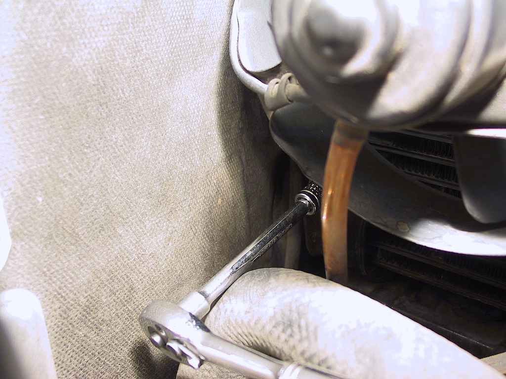
...one at the upper left...
...and one at the bottom:
Once you get the bolts out, the fan can easily be removed.
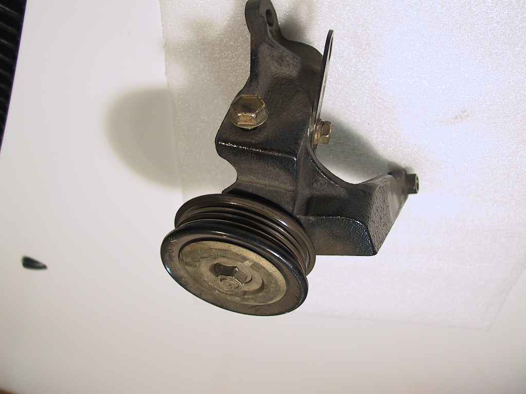
...while the second view shows the mounting holes more clearly:

Once the belt has been loosened, remove it off the pulleys.
This one proved to be problematic to reinstall.
Once the bolts are out, carefully ease the idler pulley up and away
from the intercooler. My goal was to remove the stock intercooler
undamaged, so it was a bit more time-consuming to remove it.