|
Last Updated
24 February, 2005
|
|
|
Back to Start
Page
 1
2 3
4 5
6
7
8
1
2 3
4 5
6
7
8
 |
|
|
Rebuilding the 3SGTE (continued)
Oil and Cooling Systems |
|
|
|
|
| |
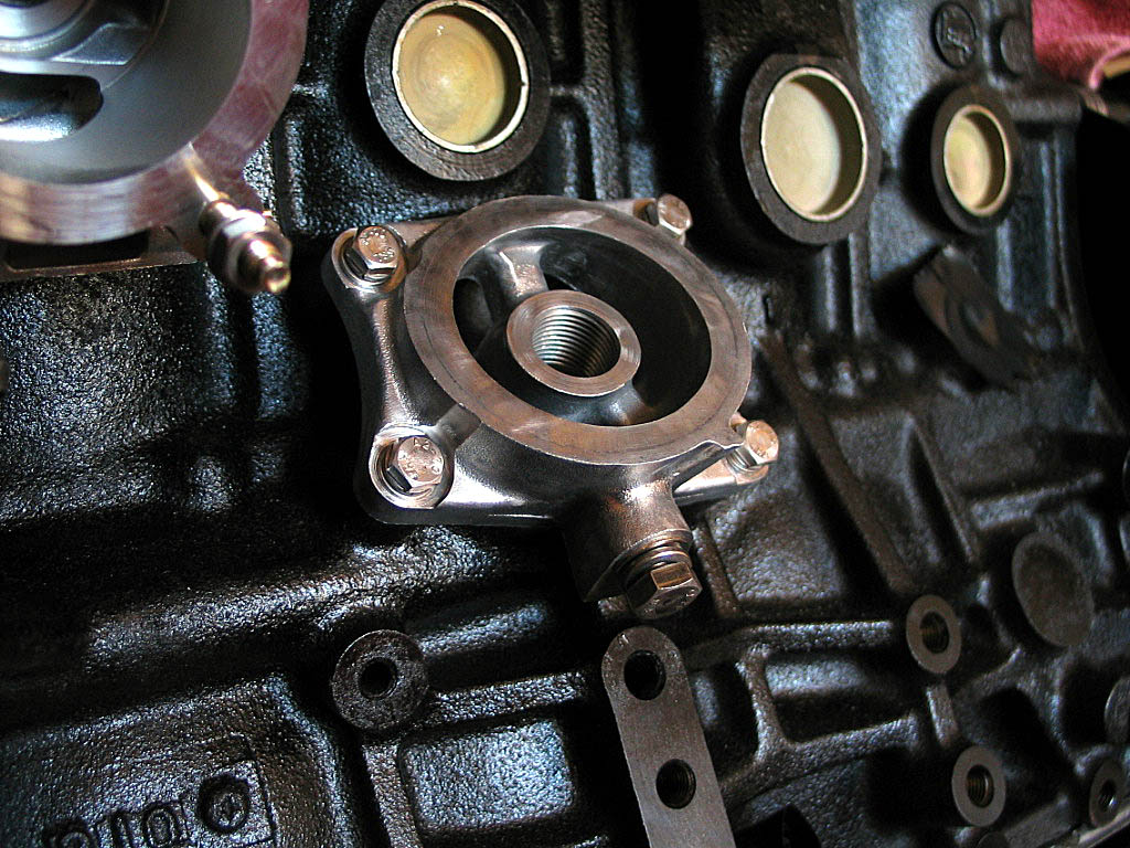
Next came the cooling system components.
There's a base for the oil cooler
(Toyota calls it the "oil cooler bracket") that needs to be installed
first:
|
|
|
Apply a little motor oil to new O-rings, then attach the
base with four bolts.
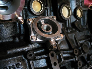
Torque the bolts to BGB specs.
|
|
| |
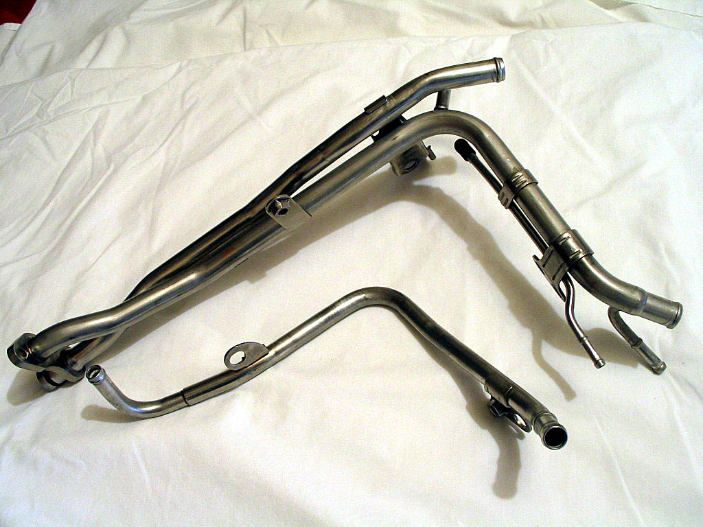
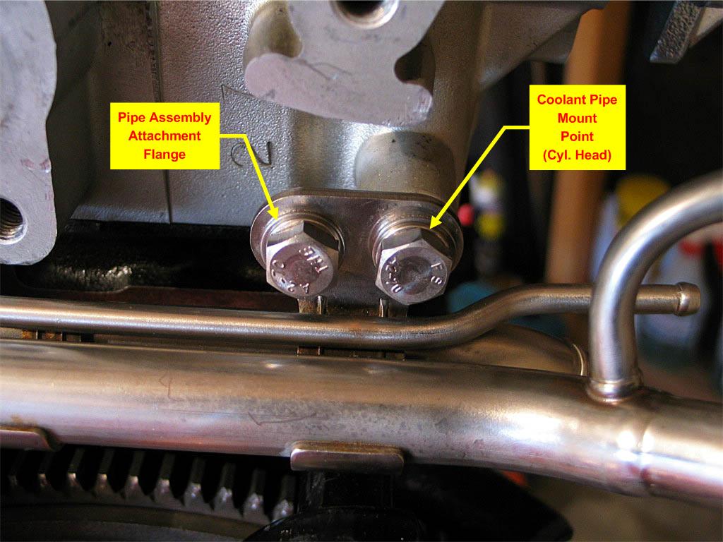
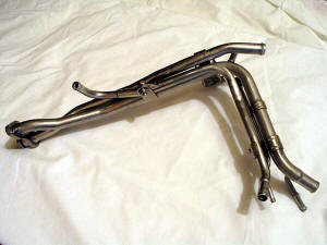
There are a couple of coolant pipes that Toyota calls
"water by-pass pipes". Here's a photo:
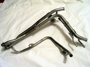
The pipe assembly on top consists of two pipes brazed together, and Toyota
calls this assembly "Water By-Pass Pipe No. 1". The single pipe below it
is unidentified in both the Toyota Electronic Parts Catalog (EPC) and the
BGB. It bolts to the No.1 bypass pipe at two flanges, as shown below:
Here's the resulting assembly:
|
|
| |
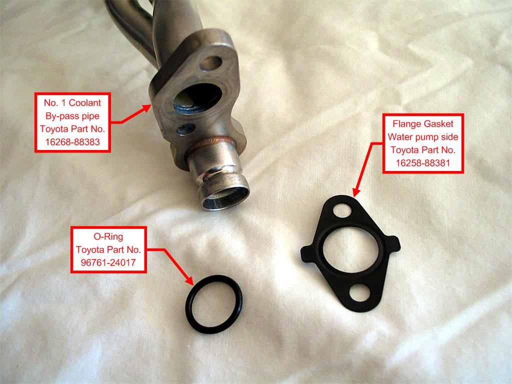
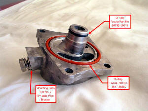
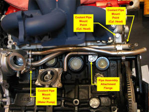
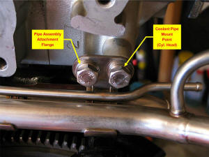
The No. 1 bypass pipe attaches to the water pump with
both an O-ring seal and a flange gasket:

|
|
| |
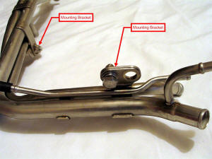
Install a new O-ring, and apply some soapy water to it.
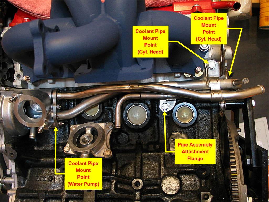
Install a new gasket, and insert the pipe into the water pump. There are
two mounting brackets that help support the pipe assembly:
Loosely attach the bolts that secure the mounting brackets, and the
M6 nuts on the water pump flange.
Tighten the nuts on the water pump first, as that will draw the pipe
into the water pump and help to align the mounting brackets. Once
everything is aligned, tighten down the mounting bracket bolts to BGB
torque specs.
|
|
| |
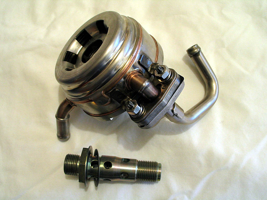
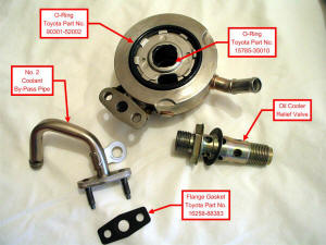
The oil cooler can now be installed. There are several
components:
|
|
| |
Loosely attach the No. 2 coolant bypass pipe to the oil
cooler flange. Tighten the nuts just enough to prevent the pipe from
falling off, as you'll need some play. Don't forget a new gasket.
|
|
| |
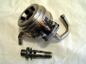
Apply a little oil to the O-ring surfaces, and to the
threads on the relief valve, and thread the relief valve on. Don't tighten
it yet:

Those two pipe ends will be connected with the No. 6 Coolant Bypass Hose
(Toyota Part No. 16283-88381), affectionately known as the "Hose From
Hell".
|
|
|
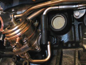
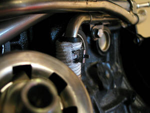
Remove the heat sleeve and clamps from the Hose from
Hell, and apply soapy water to the inside surface. Also apply soapy water
to the two pipe ends. Force the hose as far as you can onto the upper pipe
end:
|
|
|
|
Now slide the heat sleeve and clamps back onto
the hose:
|
|
|
NOTE: The two spring clamps have little clips on them to keep them in
the open position. Try not to lose them, as you'll make your job much
harder:
|
|
|
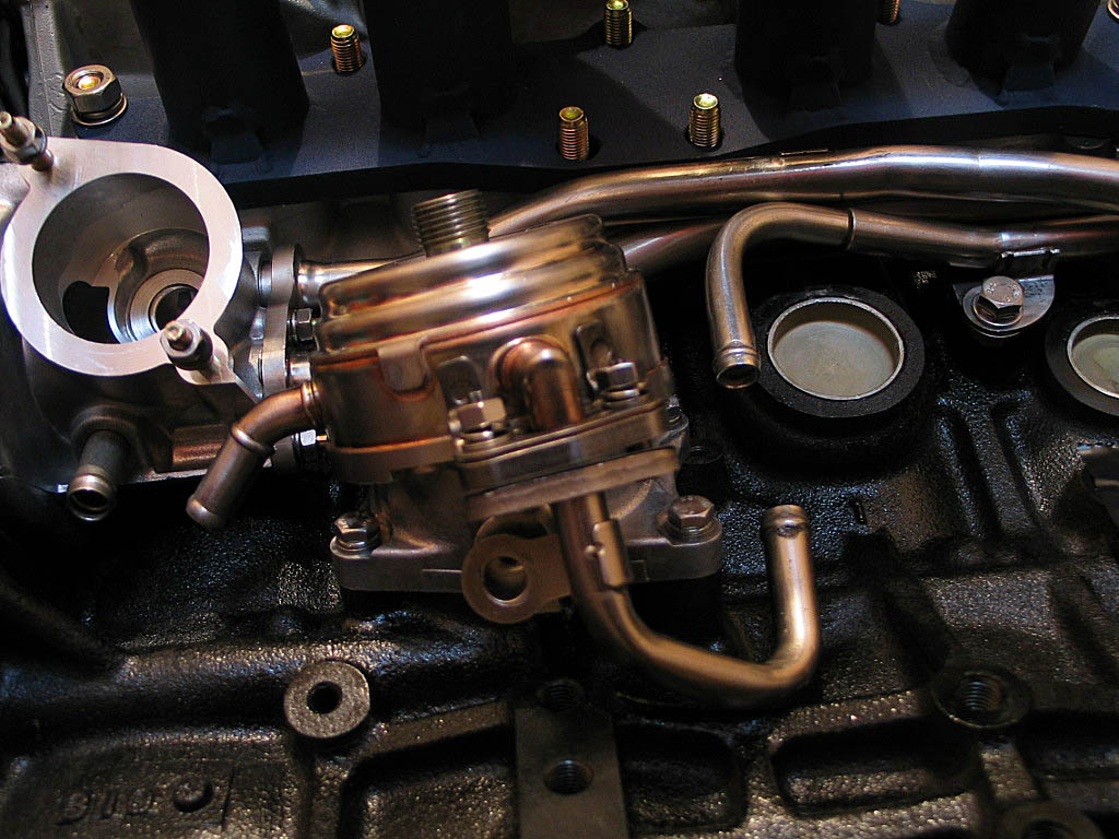
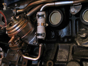
Now position the end of the No. 2 coolant bypass
pipe under the hose, and slide the hose down onto the pipe. Try to get the hose
evenly positioned onto both pipes:
Once the hose is in position, remove the clips from the clamps to secure the
hose.
The BGB doesn't describe this installation, but I'm assuming that the worm-drive
clamp's purpose is to prevent the heat sleeve from sliding out of position, and
possibly to restrict the hose from expanding too far under heat. I simply
tightened the clamp until it didn't move around.
|
|
| |
Next, torque the two nuts on the oil cooler
flange to correct specs. Then you can torque the relief valve down, using a 30mm
thin wall socket. Finally, tighten the bolt that holds the bracket
on the No. 2 bypass pipe to the oil cooler base.
|
|
| |
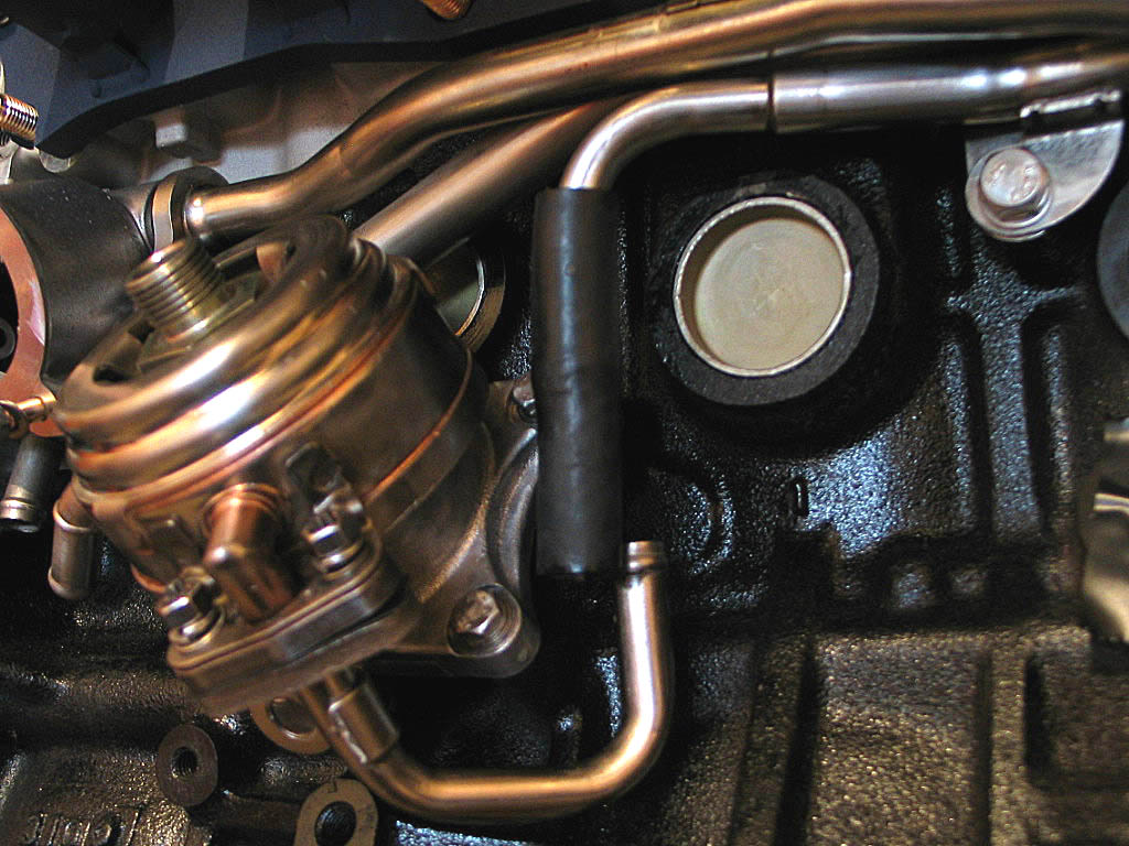
There are a few engineering choices on the MR2 that make you scratch
your head (or worse), but this is probably the number one frustration.
Installing this hose was a bit of a hassle, even with the engine up on a
stand. Now imagine it failing in real life....
It's usually covered in road grime and spilled oil from umpteen oil filter
changes. Now it's coated in slippery anti-freeze. It's located under the
exhaust manifold, and behind the catalytic converter, so you are working completely blind. And the weather's
probably hot as hell, as that's when hoses tend to fail. Every tool you
have just isn't quite right to get at the clamps, and the hose is
probably sticking to the pipes and reluctantly coming off in little
pieces, due to the hard life it's had. Getting the new one on is at
least as bad as getting the old one off, as the clearance between the
pipes is so tight. It truly deserves the name "Hose From Hell"
Just the thought of going through this makes me want to replace this
hose whenever I have free and clear access to it! For about $3, it's
worth having a spare around for just that purpose.
I had considered avoiding this problem for good, by using a remote,
air-cooled oil cooler. However, that introduced additional cost, and
finding a location for the remote cooler that had good airflow was a
complication I didn't want to deal with.
|
|
|
|
There's another hose that runs from the oil cooler
to the water pump. Toyota calls this the "Water By-Pass Hose No. 5" (Part No.
16282-88380):
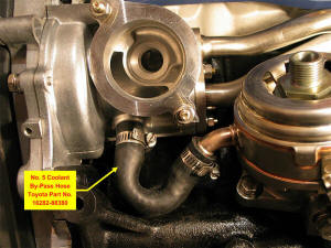
You'll need soapy water and some finger strength on this one as well. You'll
need to twist the hose on the pipes to avoid getting a kink, as Toyota did not use
a pre-formed hose for this. Tighten the hose clamps firmly, but not too tight,
if you are using worm-drive clamps. Many people use far too much torque on those
clamps. Worm-drive clamps with a �"-wide band only need 40 inch-pounds of
torque. The smaller 5/16"-wide versions only need 15 inch-pounds of torque.
|
|
|
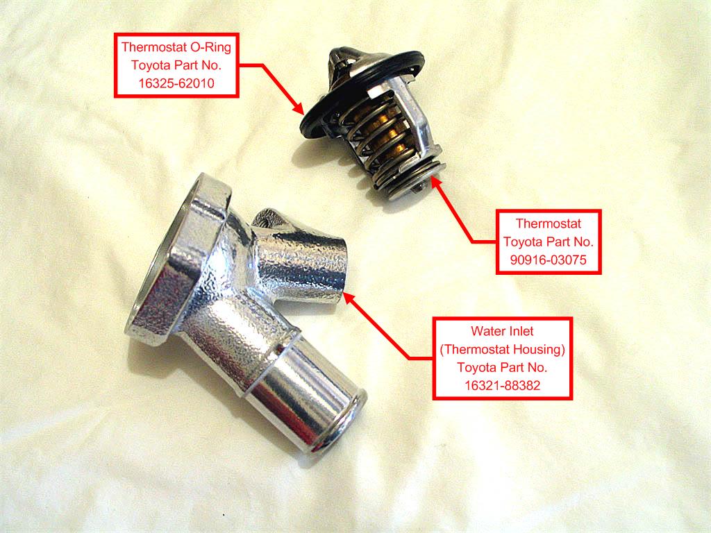
Next up is the thermostat and water inlet (thermostat housing):

If you purchase a new thermostat, a new O-ring comes with it.
|
|
|
The thermostat has a jiggle valve that must be
aligned with a tab on the housing:
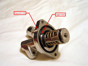
The BGB says the alignment must be within 5�
on either side of the tab.
NOTE: The stock parts are not as pretty as this water inlet. I had it ceramic
coated with some other parts to fill out an order with the coating shop.
|
|
| |
The inlet slides onto the two studs on the water pump. Attach the water inlet,
taking care not to disturb the alignment of the thermostat to the tab. Tighten
the two M6 nuts to the recommended torque. There's also a plug on the inlet that should be
installed if it's been removed or you've replaced the inlet.
|
|
| |
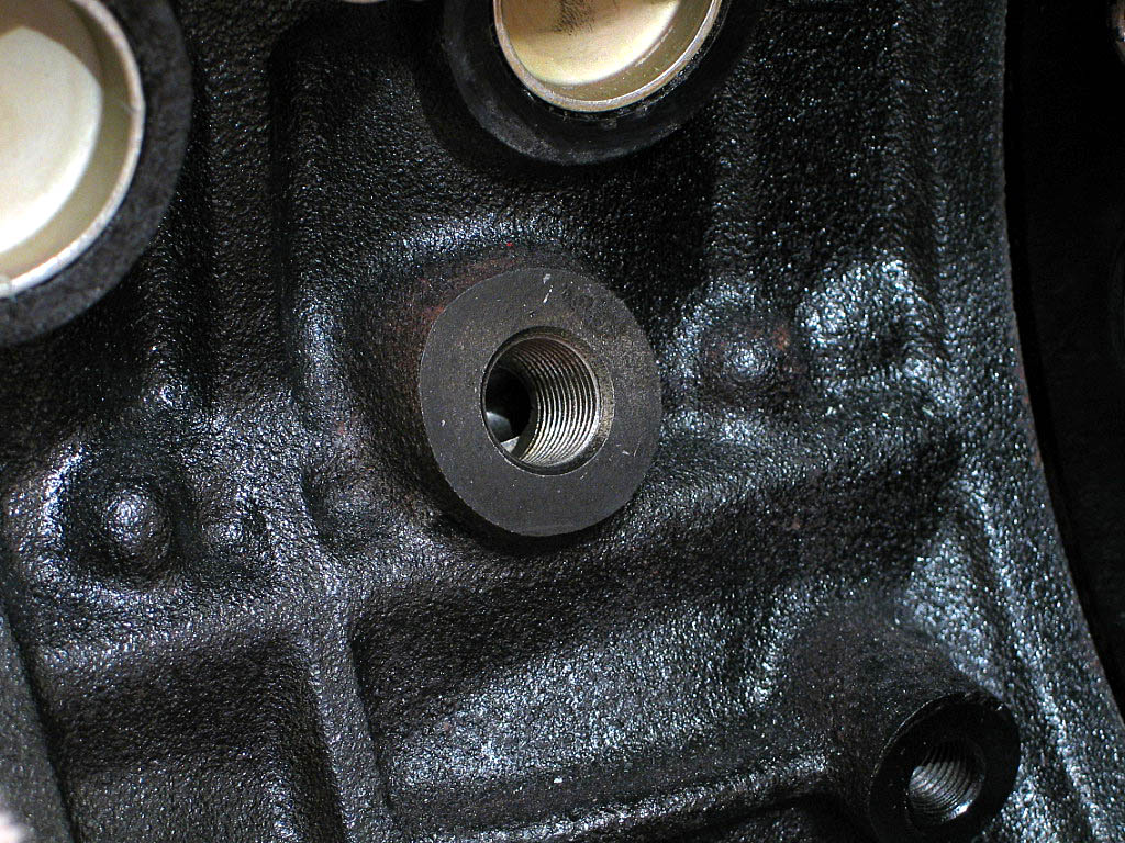
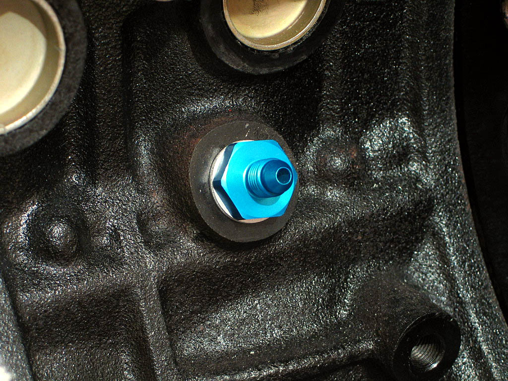
Since I'm installing an aftermarket turbo (GT30), I'll be using
stainless hoses and aircraft fittings for the cooling and oil lines. I
needed an adapter to replace the OEM banjo-bolt fitting for the oil supply
opening on the engine block:

|
|
| |
I had difficulty finding the correct adapter in the U.S., as I did with
all of the metric fittings. I found a U.K. firm,
www.ThinkAuto.com, that carried all
of the fittings I was looking for. They weren't cheap, but then none of
these aluminum aircraft fittings is cheap. Here's the adapter I
used:
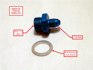
The step-down from M18 to -4 AN was the key factor. I already had the oil
supply line that came with the turbo kit, and it used -4 AN fittings. The
U.S. suppliers didn't seem to offer this specific adapter configuration,
although KO Racing offers an M18 -
to -3 AN adapter.
|
|
| |
I used a couple wraps of
Teflon tape on the threads, then tightened it down enough to seat the
crush washer:

|
|
| |
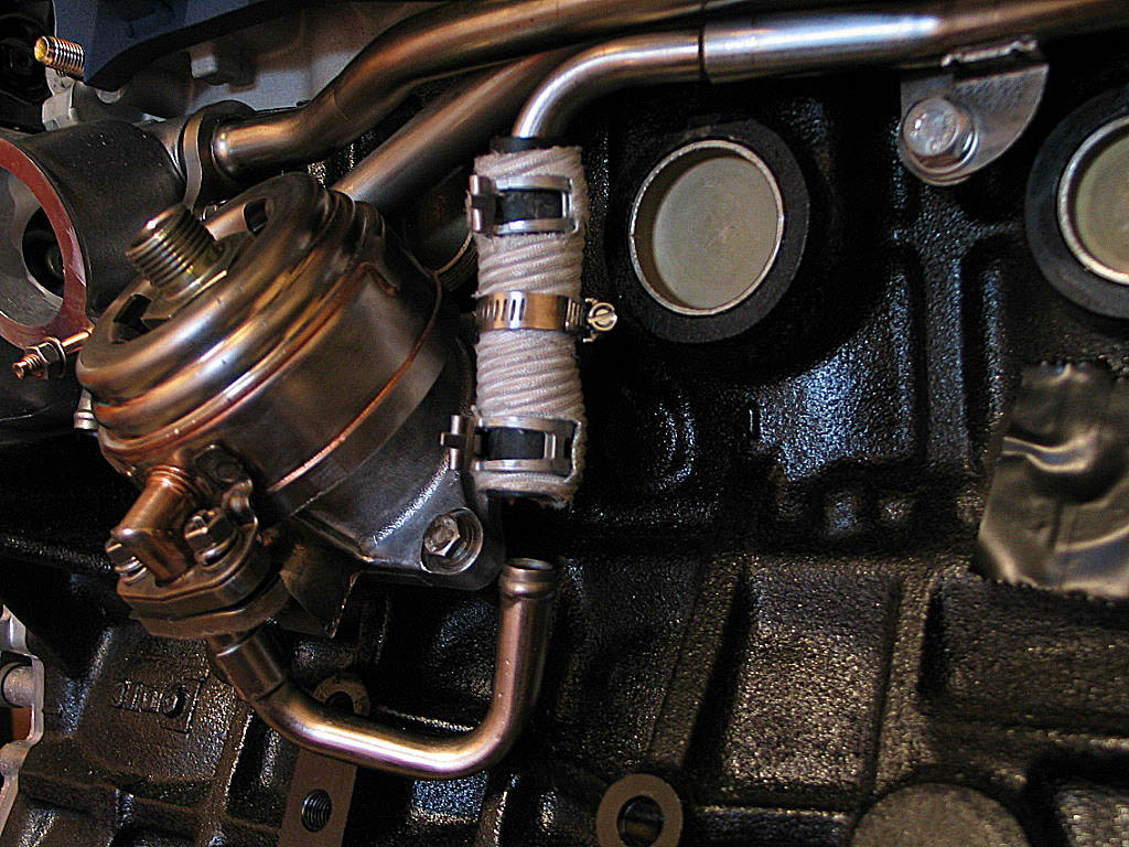
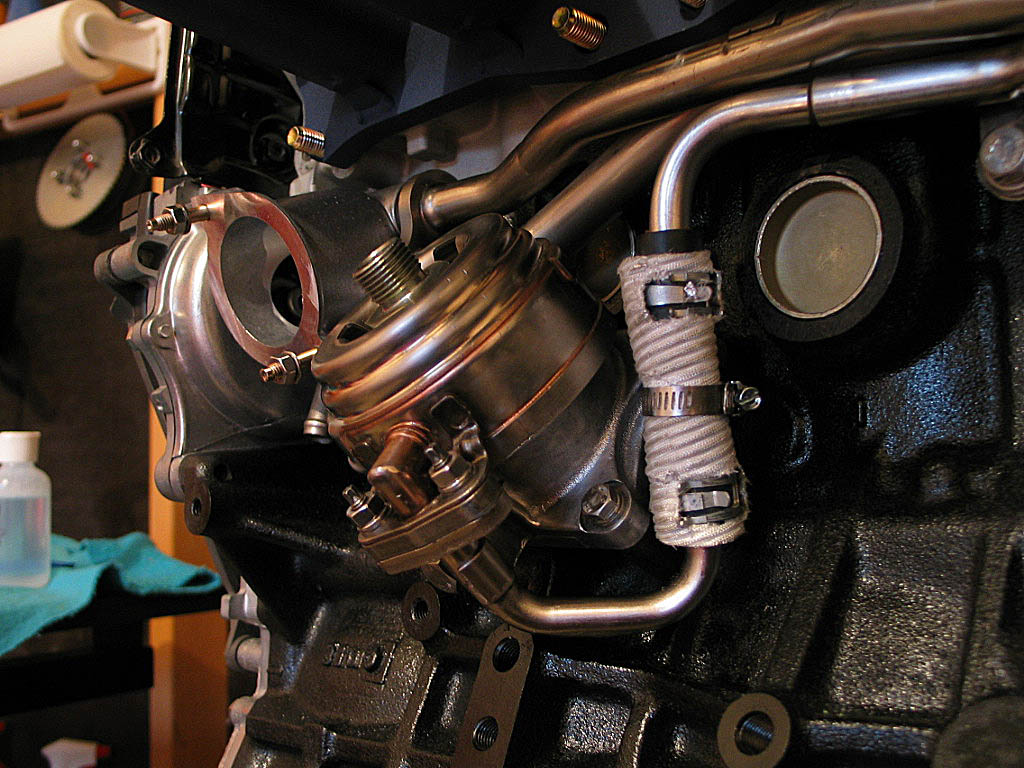
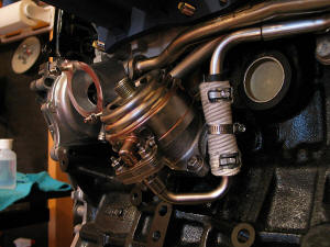
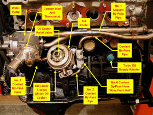
OK, here's the exhaust side of the motor after all this assembly, with
the key components identified:
|
|
| |
Continued on next page... |
|
|
|
|
|
Back to Start
Page
1
2 3
4 5
6
7
8
|
|
|
|
|
|
|
|
|
|
|