|
Last Updated
14 September, 2004
|
|
|
Back to Start
Page
 1
2 3 4 5
6
7
8
1
2 3 4 5
6
7
8
 |
|
|
Rebuilding the 3SGTE (continued)
Turbo Components |
|
|
|
|
| |
I could now start installing some of the turbo components. I had dry-fit
some of them to check for obvious problems, but now I could begin
assembling the pieces permanently.
|
|
| |
Much of the delay I had with my turbo kit had to do with waiting for
fittings and hoses. As it turns out, I never got some of the required
fittings. At that point, I was exhausted from my efforts to get
eXtremeBoost to provide the parts I had paid for, and simply decided to
obtain the correct parts myself.
|
|
| |
The turbo is a Garrett GT30R, with the following specs:
Compressor
● Housing A/R = .70
● Wheel Trim = 52
Turbine
● Housing A/R = .82
● Wheel Trim = 84
|
|
| |
The GT30 center section has four ports for fluids. Two are coolant ports
(supply and return), and these appear to be threaded for -6 AN female
O-ring fittings.
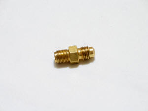
Adapter fittings for the coolant ports were included with my kit:

These had -8 AN male fittings for the hoses. I also received the coolant
hoses, one with a straight -8 AN fitting and one with a 90˚ -8 AN fitting.
|
|
| |
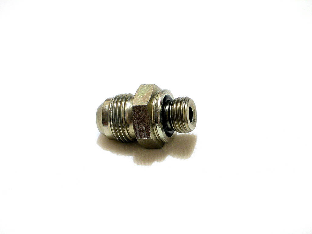
There are two ports for oil on the GT30 as well. The oil supply is
threaded for a �" - NPT reverse flare. Unfortunately, the correct fitting
was not included in my kit. Luckily,
ATP Turbo carries all
kinds of components for turbo installs. They provided me with the missing piece.
Here's the oil supply adapter:
This adapter has a -4 AN male fitting for the oil supply hose.
It also has a .035" restrictor hole in it to prevent too much oil from
reaching the bearings and leaking past the seals. My kit DID include the
correct oil supply line, about 18" long, with
one straight and one 90˚ -4 AN fitting.
|
|
| |
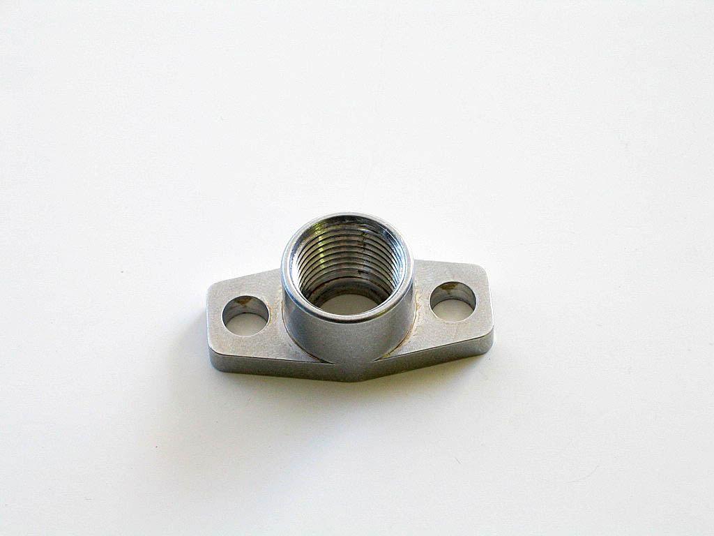
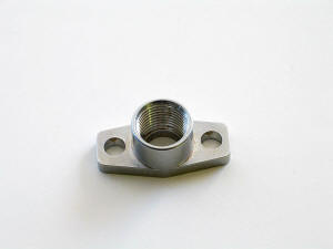
The oil return uses a flanged adapter that connects to the center section
with two M8 bolts, and is threaded for a �" - NPT fitting. I didn't
receive this adapter in my kit, either, but ATP provided it, as well as
the gasket.
This adapter required a hose end with a �" - NPT male fitting:
|
|
| |
Because there is so little room on the turbo's center
section, I installed the water adapters and oil supply adapter before
attaching the turbo to the exhaust manifold. The oil return adapter could
be installed afterward.
|
|
|
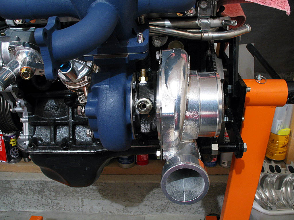
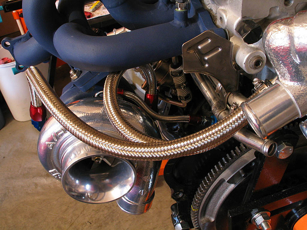
I hung the turbo assembly from the manifold:

|
|
|
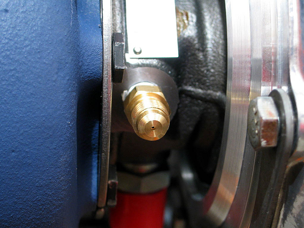
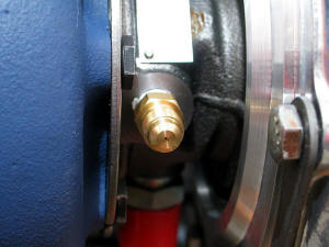
Here's a look at the oil supply adapter, showing the
restrictor hole:
|
|
|
|
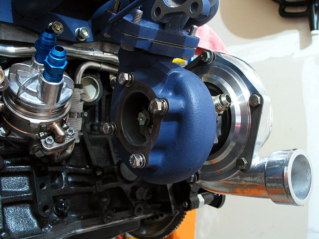
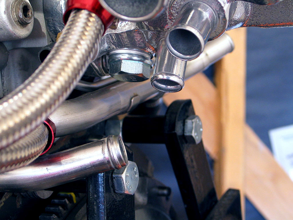
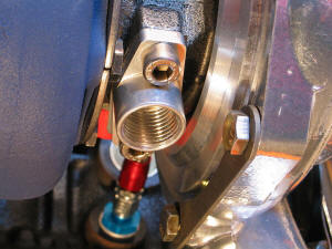
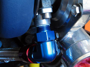
The oil return, which is opposite the supply
port, needs to be facing downward to
ensure proper drainage. Due to the tight quarters, aligning the turbo sections
into the correct alignment ("clocking") requires care. It would be
easy to damage one of the fittings when tightening the housing bolts:

Here's the final position for the fittings.
There's not a lot wiggle room when trying to make everything fit, but sometimes
a difference of 1/16" is just enough. This keeps the oil return port pointing
down for good drainage.
|
|
|
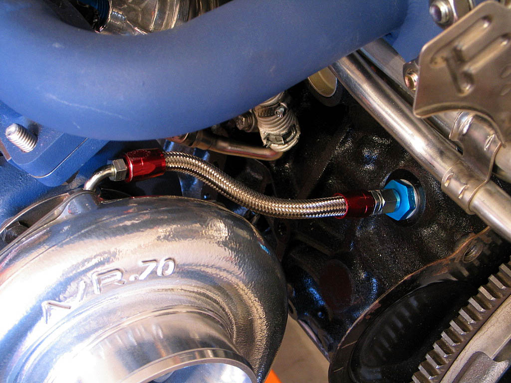
The oil supply line I received was about 18" long, but I only needed
about 6". I thought I could use one of the existing ends, but
after inspection of the assembled hose end I felt uneasy about its
quality. I knew I would feel more confident if I reassembled the ends
myself.
I cut the hose to about 5�" long, and assembled the ends onto it. I then
connected both ends:
|
|
| |
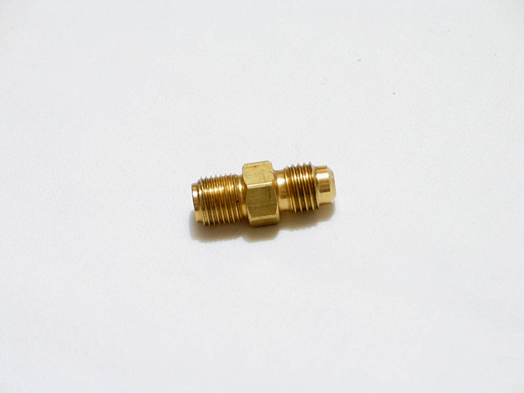
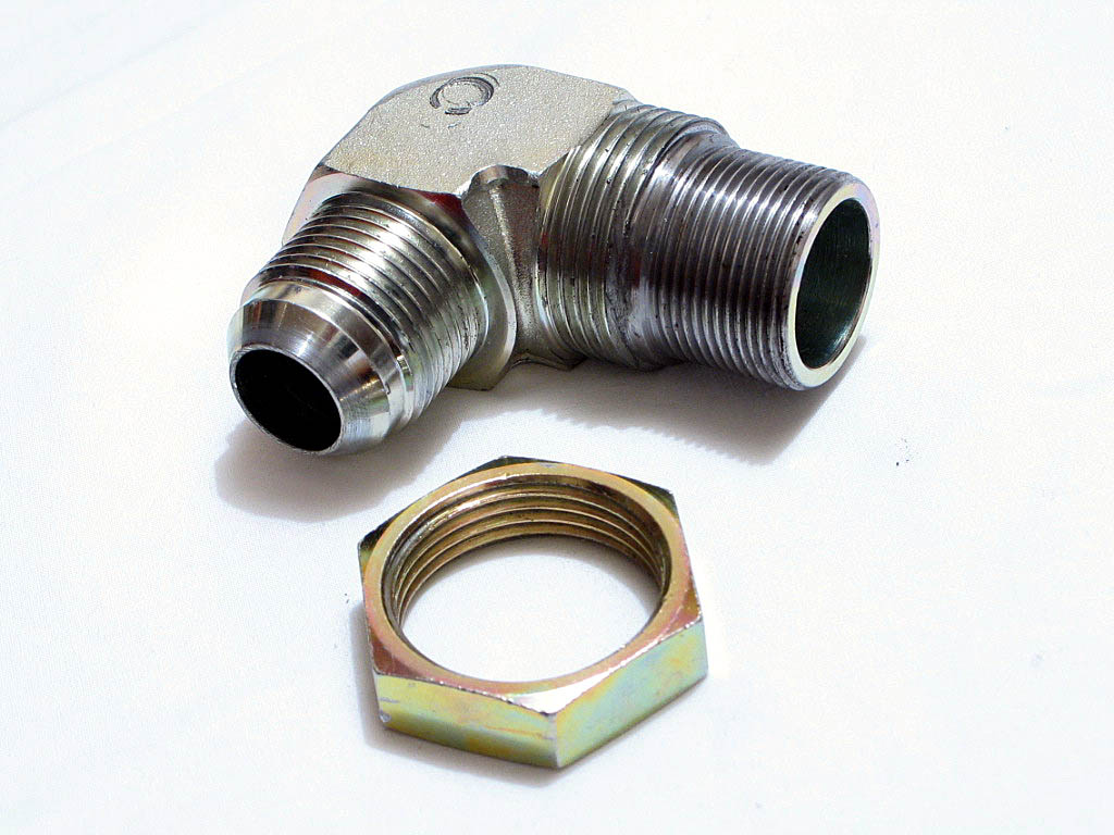
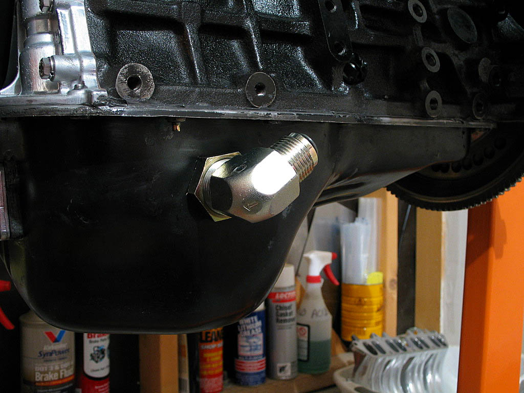
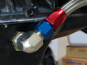
One important fitting that came with my kit was the large
90˚ adapter for the oil returning from the turbo
to the oil pan:
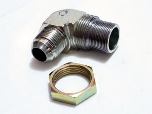
This steel fitting has a large (M30?) fine thread male end and lock nut for the oil pan, and
a -12 AN male end for the drain hose.
KO Racing offers a straight
fitting for this purpose.
|
|
| |
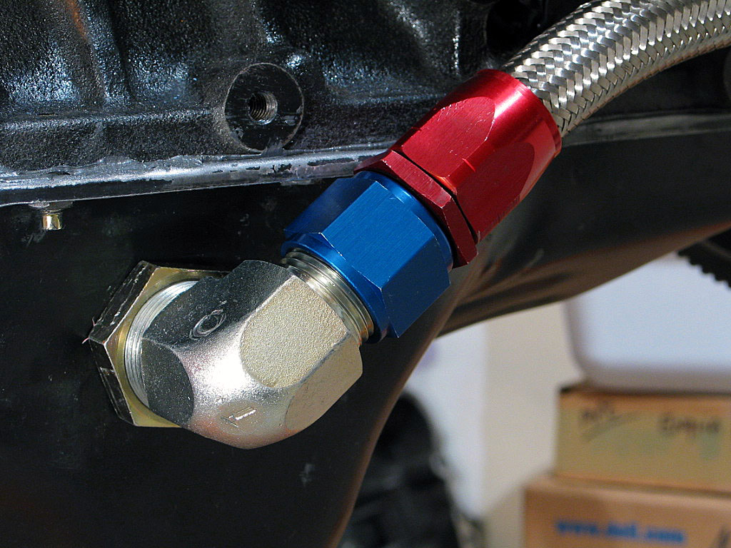
There's just enough clearance with the lip of the oil pan to fit the adapter and
hose:
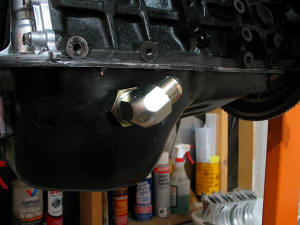
The position shown should clear the A/C compressor. If not, a minor
adjustment should do the trick. Since the stock catalyst will be gone, I
shouldn't
have any other clearance issues.
|
|
| |
Next, I attached the oil drain adapter, with a new gasket. I used socket head
screws and high-temp thread lock:
This fitting uses a �"-NPT thread.
|
|
| |
I cut the -12 AN hose to fit the 90˚ hose adapter
I bought to fit the oil drain flange fitting. However, after assembling the
hose, I discovered there was insufficient clearance to get a wrench on the hose
end that fit into the flange. I removed the flange and secured it into a vise. I
applied some Teflon thread sealant to the hose end and tightened it into the
flange.
I cleaned off the flange bolts, applied some new thread locking compound, and
reinstalled the flange adapter with the hose end already in place:
|
|
| |
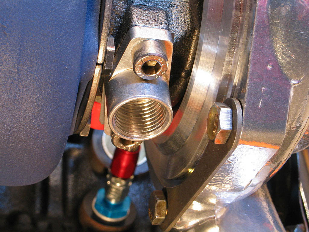
I then attached the other end to the oil pan fitting:
|
|
| |
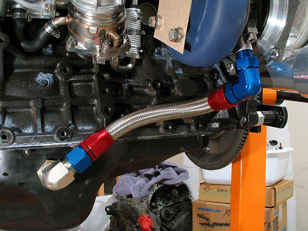
And here's the result:

|
|
|
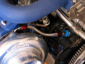
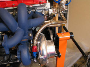
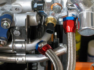
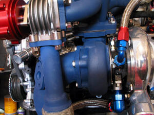
Next came the coolant lines.
Only one of the hoses in the kit had a 90� end, but I could see that I would need 90� ends on
both of them, so I bought a new fitting for the other one. Just one of the many
shockingly expensive hose fittings I would need before I was through.
I took one hose and attached it to the inner coolant fitting (the one facing the
engine block). I had to find a way to route the hose without rubbing against
other components and without bending it into too tight of a radius. The hose
manufacturers say a -8 AN hose shouldn't be bent tighter than a 3�"
radius (7" diameter), which is a pretty large loop. I cut the hose to length with a cutoff
disk on my die grinder, and connected it to the Coolant Bypass Pipe No. 1.
I replaced the straight hose fitting on the other hose with the new 90˚ fitting,
and installed it to the outer coolant fitting on the turbo. The other end was
connected to the coolant outlet housing:
|
|
| |
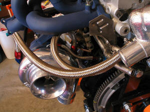
After I took these photos, I bought a couple of Spectre "Magna Clamps" to use in
place of the plain-jane stainless worm-drive clamps:
Unfortunately, these fancy ends take up a lot of space, so I had to mount one of
them upside down. The other one barely fit on the pipe, again due to its size.
I may ultimately remove them in favor of standard hose clamps, as they might be
a bit too "ricey". The good news is that they cover the frayed ends of
the stainless braid better than the standard clamps.
|
|
| |
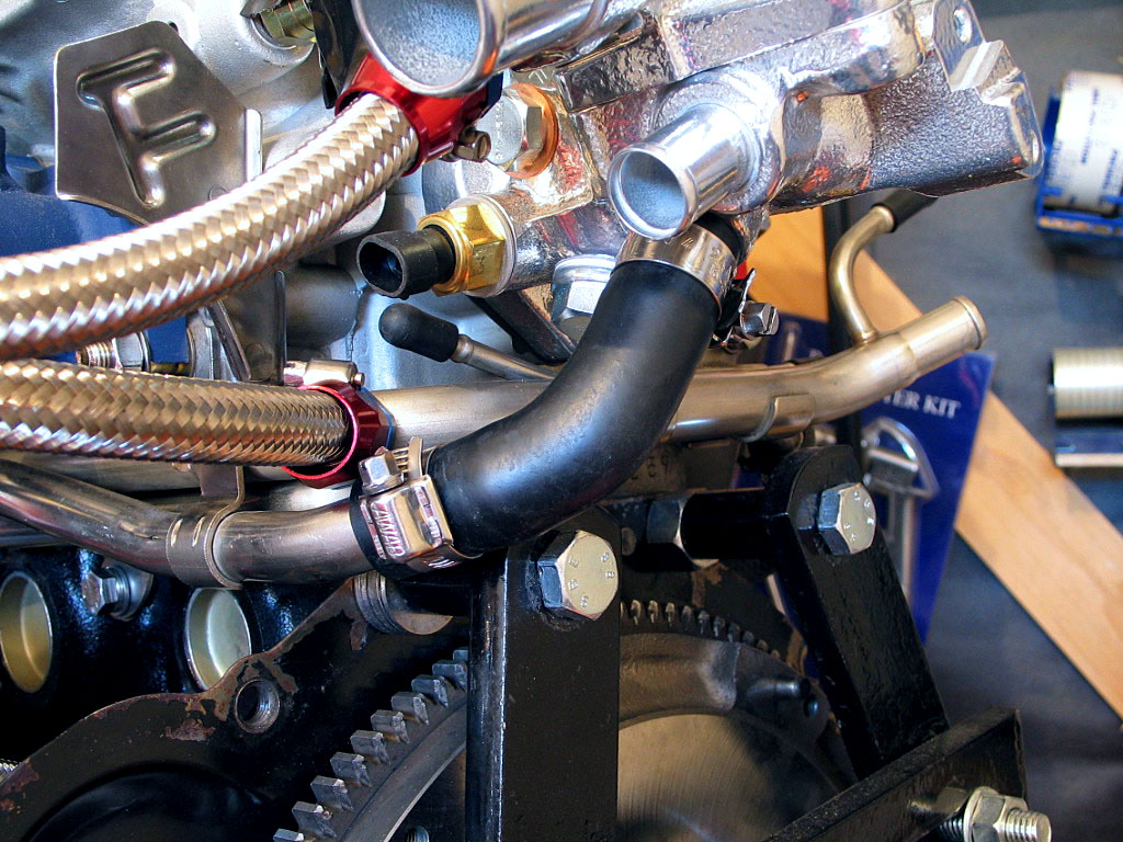
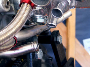
There's yet another bypass hose to install, which connects the bypass
pipe to the coolant outlet housing:
|
|
| |
Again, some soapy water helps fit this hose into position:

This hose is identified by Toyota simply as "Hose, Water By-pass", Part No. 16261-88361.
|
|
| |
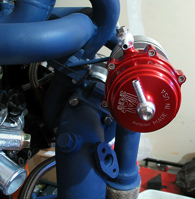
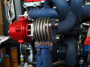
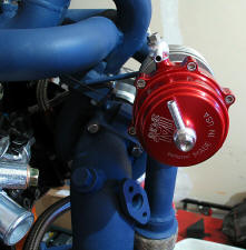
The next step was to attach the downpipe and wastegate. I was still
waiting for the turbo outlet gasket, so this was just a dry fit.
The exhaust inlet on the 46mm Tial wastegate is on the bottom, and this
is attached to the exhaust manifold. The outlet (dump) port is
attached to the downpipe:
|
|
| |
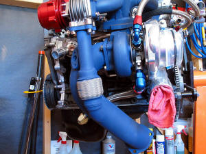
There are two manifold vacuum/boost connections on the wastegate. The side port needs
to be connected to the throttle body before the throttle plate. The top
port will be connected to the boost controller:
 |
|
| |
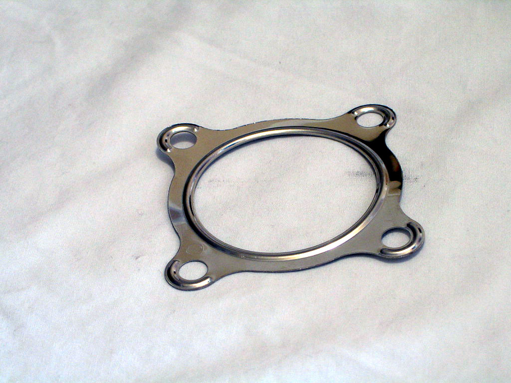
The turbine-to-downpipe gasket arrived a few weeks later:

I installed the gasket and tightened everything into place, using
hi-temp thread sealant on the threads, and hi-temp,
precipitation-hardened, stainless-steel Belleville washers:
|
|
| |
Continued on next page... |
|
|
|
|
|
Back to Start
Page
1
2 3 4 5
6
7
8
|
|
|
|
|
|
|
|
|
|
|