|
Last Updated
14 September, 2004
|
|
|
Back to Start
Page
 1
2 3 4 5
6
7
8
1
2 3 4 5
6
7
8
 |
|
|
Rebuilding the 3SGTE (continued)
Fuel and Intake System - Part 1 |
|
|
|
|
|
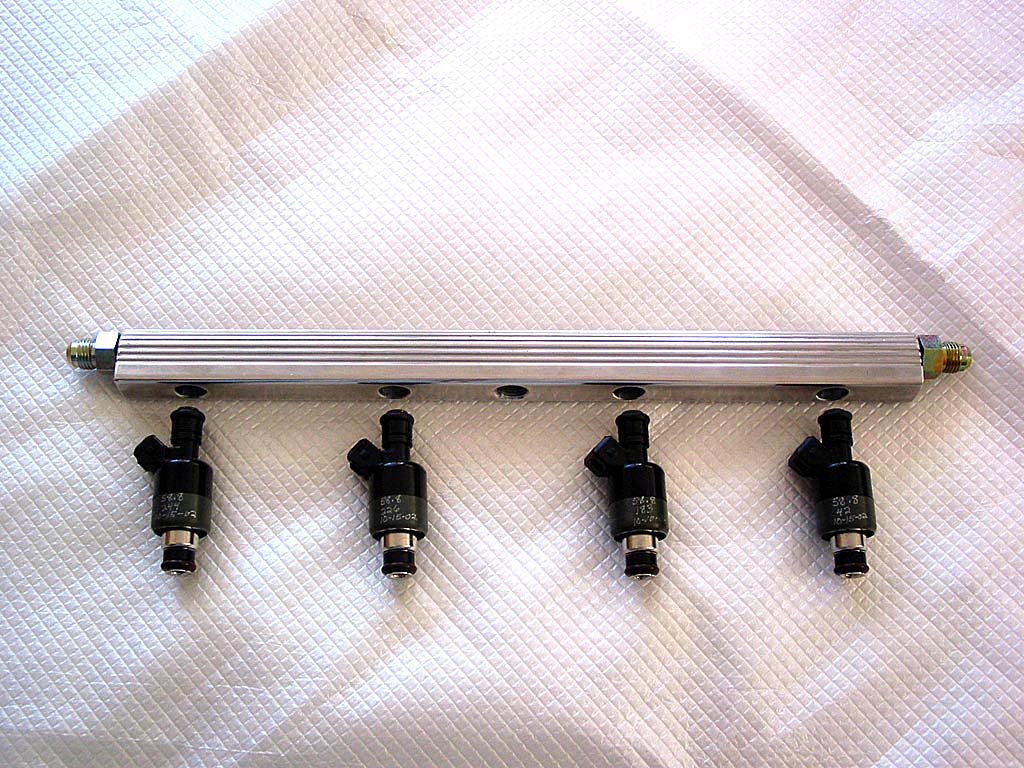
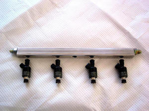
The fuel rail and injectors came next. I purchased 65
lb/hr Delphi top-feed, low-impedance injectors (Part No. FJ10473) from
Garage Advance, along with a custom aluminum billet dual-feed fuel
rail. This was another case where I should have checked the fitment after
receiving the parts, but they sat around for over a year, and Garage
Advance is apparently out of business now.
According to the TECł Wintec software,
65 lb. injectors are just about right for my planned mods. I planned on using a full-sequential
injection configuration, rather than phased injection. That should enable
the TECł to control the low-speed fuel delivery
yet still take advantage of the high fuel flow these injectors are capable
of.
|
|
|
|
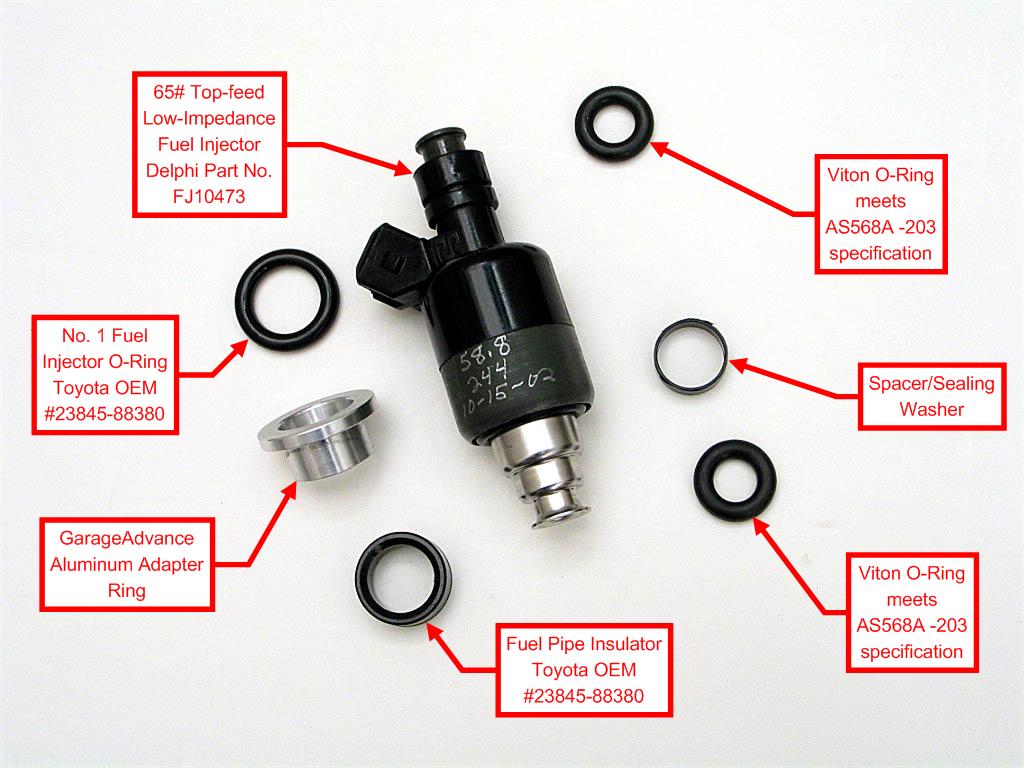
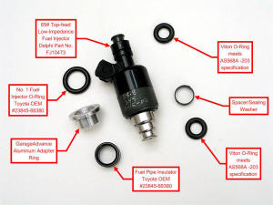
Garage Advance provided special collars for
the 3SGTE head, as well as the electrical connectors. I had a problem with the
o-rings on the top of injectors, as they seemed a bit oversize, and no matter
what I tried, they would not fit into the fuel rail. I replaced them with
standard-sized Viton o-rings. Here's a breakdown of the injector components:
|
|
|
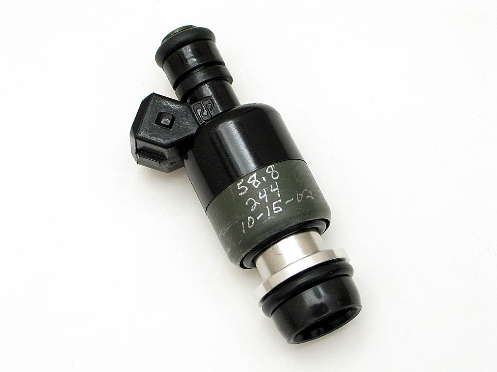
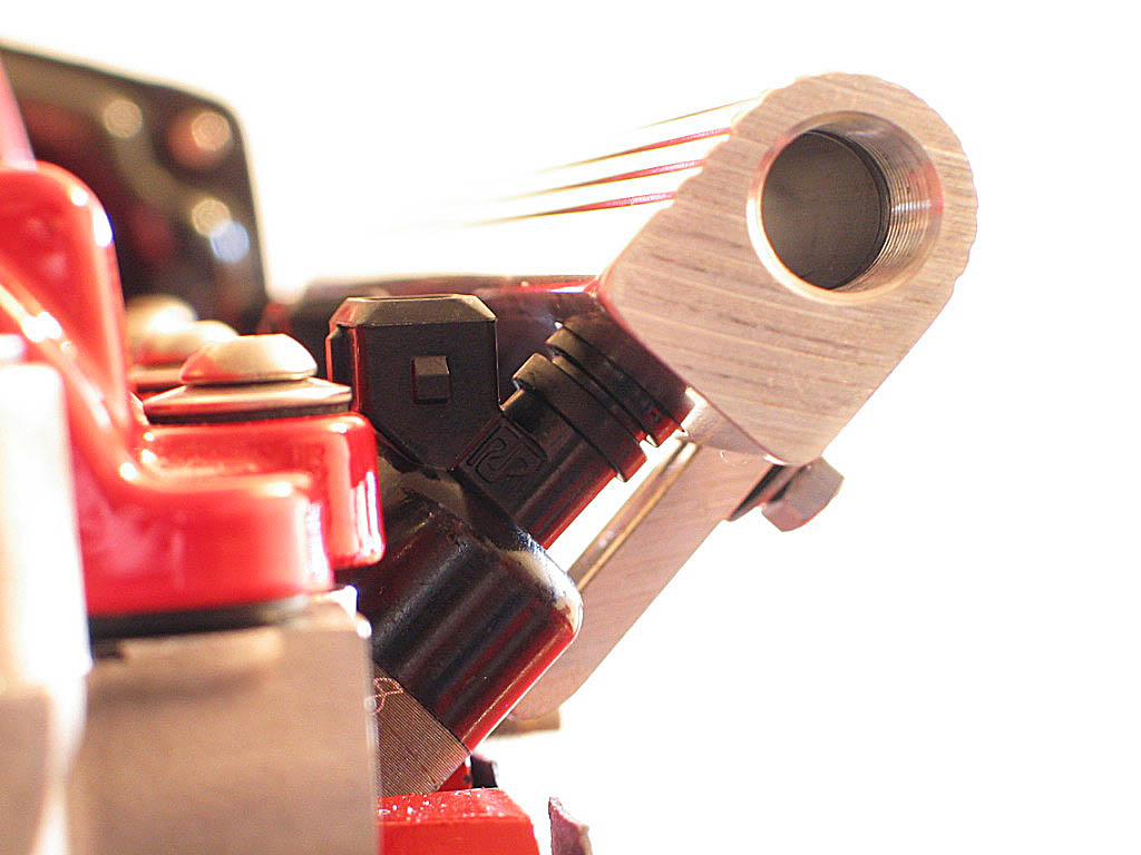
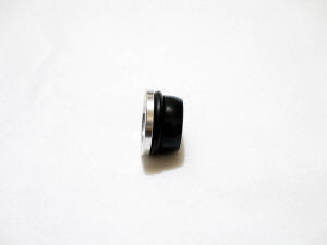
Here's the assembled injector before it gets installed into the cylinder
head:

NOTE: 65 lb/hr roughly converts to 682 cc/min. The "58.8" written on the
injector indicates its tested flow rate at 85-90% duty cycle at 43.5 PSI.
|
|
| |
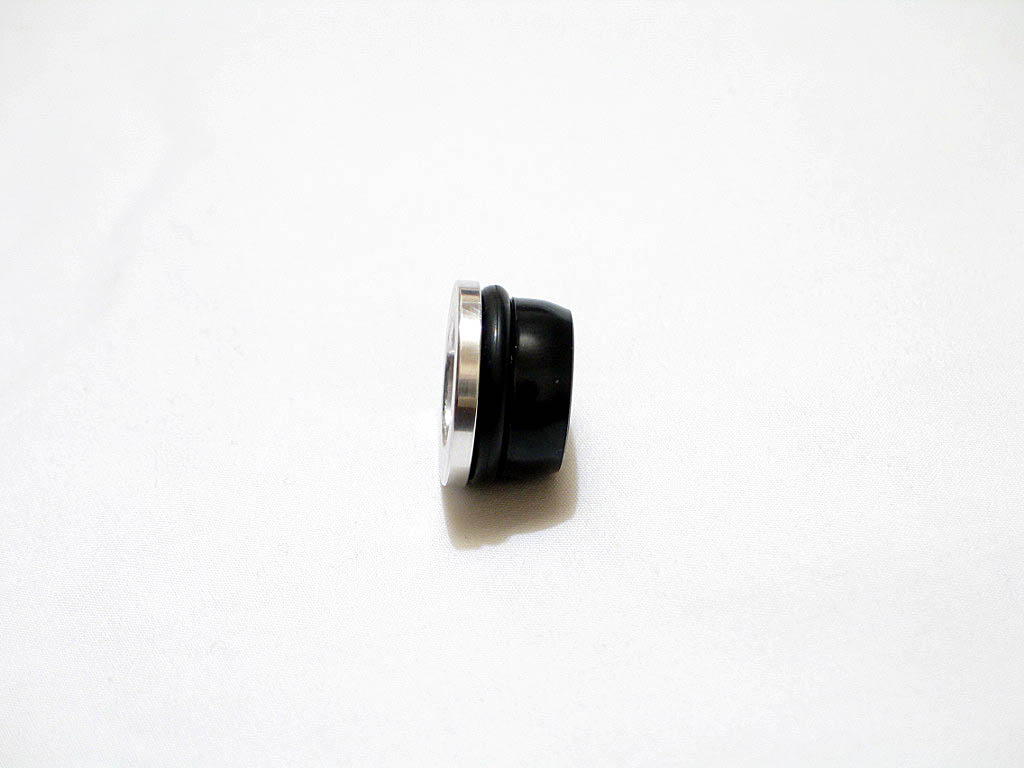
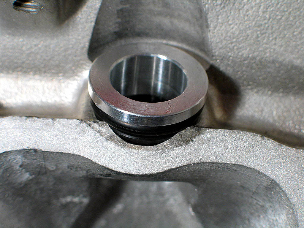
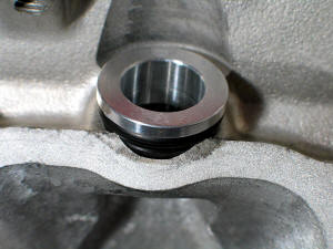
The collar assembly needs to be installed into the cylinder head
first, separately from the injector body. The collar, o-ring, and insulator
sleeve need to be clean of all dirt and oil.
The o-ring is installed first, then comes the insulator, which must be
stretched onto the collar:
|
|
| |
The collar needs to be carefully centered into the fuel injector port on
the cylinder head. Once it was positioned, I used a deep socket and
a rubber mallet to gently tap it into a fully seated position. This was much more
difficult than it should have been, as even the slightest amount of misalignment and
the collar would not seat itself properly:
I tried adding a small amount of oil to make the installation easier. It
DID make it easier, but the oil caused the collar to pop
out of the hole after a minute or two. So I fitted them all dry.
|
|
| |
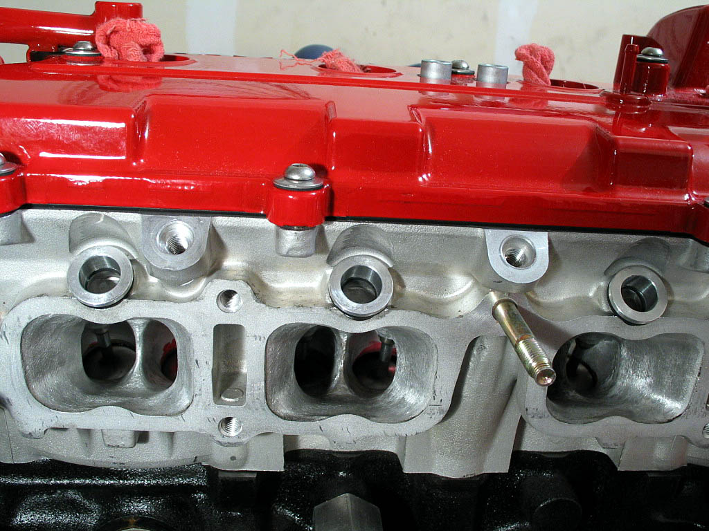
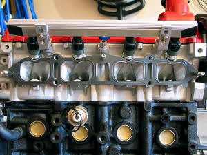
Here's a photo of the collars in place:

|
|
|
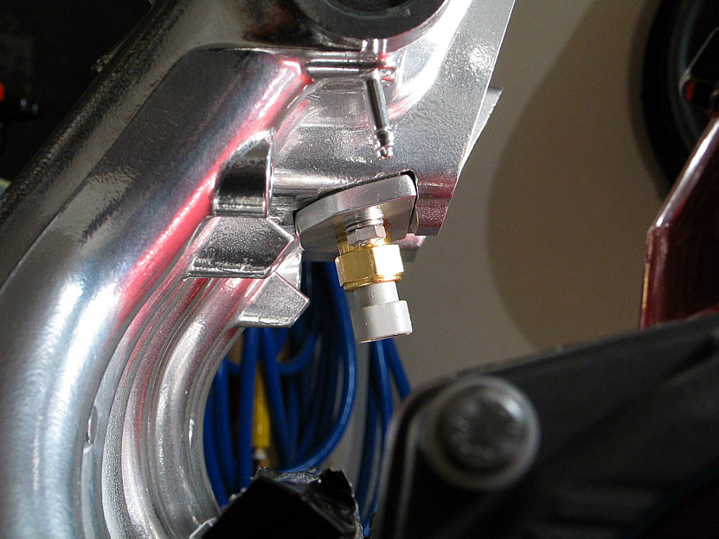
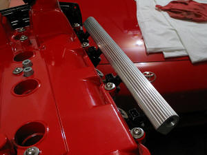
I installed the injectors and fuel rail to check
the fit, and to determine how I could best route the fuel lines:
|
|
| |
My first discovery was that one of the mounting holes on the fuel rail had been
drilled incorrectly, about 1/8" from where it should have been:
This was when I tried to reach Garage Advance to get this rail replaced, and
found out they were no longer in business.
The misalignment could have been corrected by fabricating a new mounting
bracket, and that was my intent. However, I found another problem.
|
|
| |
The fuel return hole is positioned on the bottom of the rail pointing
straight down towards the cylinder head. It requires a -6 AN 90° O-ring
fitting to clear the surrounding engine parts. Unfortunately, I was unable
to find any fitting compact enough to provide clearance for the fuel line.
No matter which direction the fitting was oriented, it interfered with
something.
The best location for the return port would have been on the back of the
rail, as that would have provided a straight shot through the runners of
the intake manifold. The top or front of the rail also would have worked.
I finally decided to block off the center port and simply feed the fuel in
from one end and use the other end as the return. This rail has a ˝" I.D.
supply, so in combination with the Supra TT pump, it would be fine for my
fueling needs. (That dual-feed looks so trick, though...).
|
|
|
|
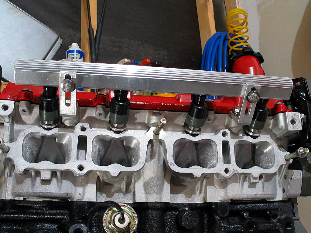
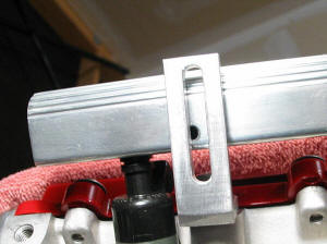
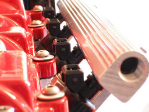
I was able to get the support brackets to align
better by slightly enlarging the mounting holes and carefully adjusting their mounting locations. Here's a shot of the rail
installed...

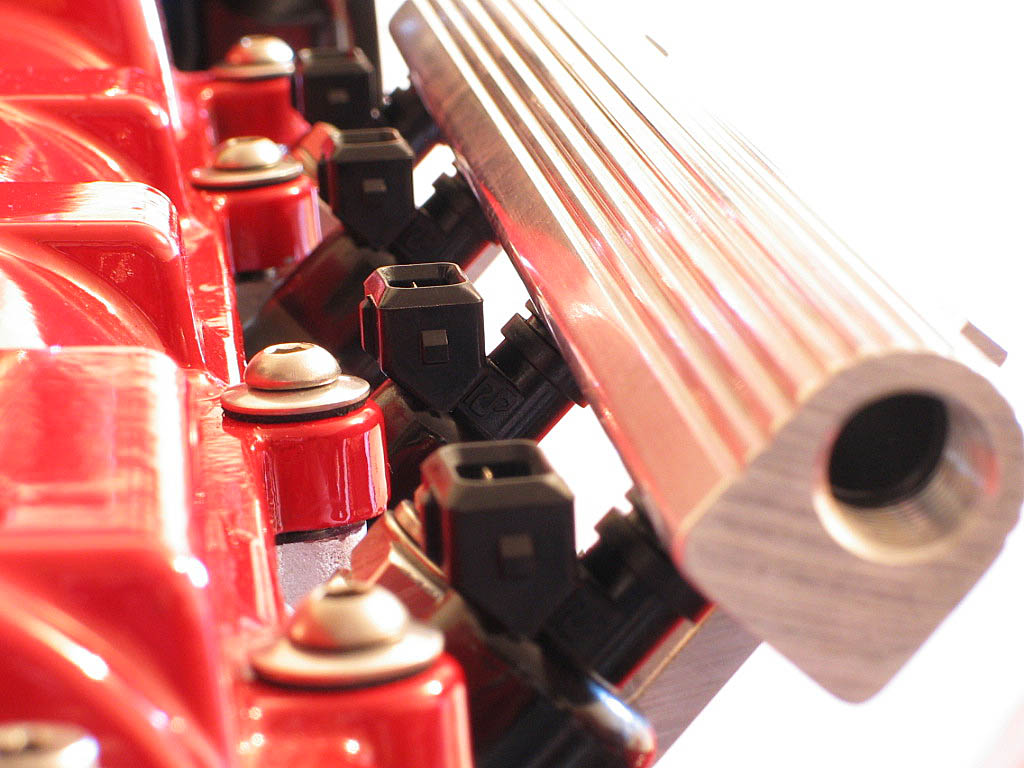
...and here are a couple of detail shots
|
|
| |
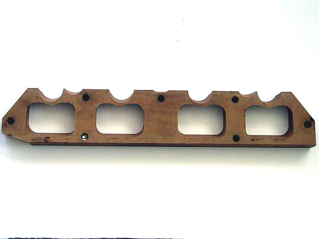
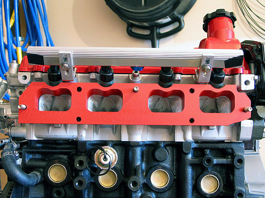
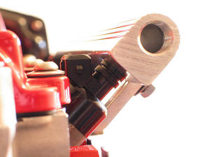
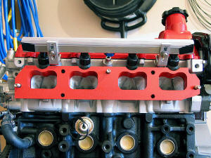
I'd purchased a combination TVIS eliminator/insulator from Manjit Gosal:
It was machined from a phenolic type of material. I painted the piece
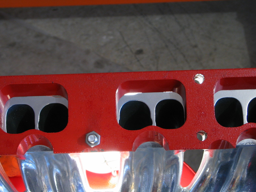
with red engine enamel. However, when I dry-fit the unit, I found there
were air gaps:
|
|
| |
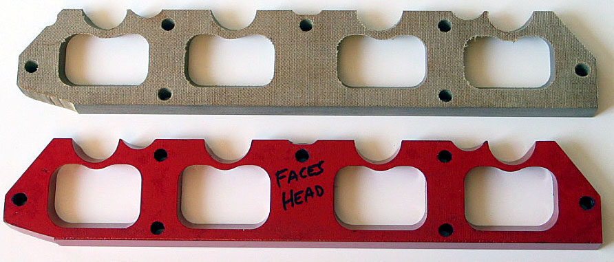
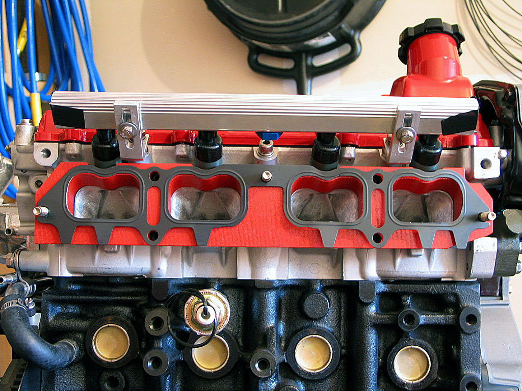
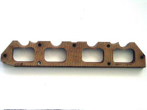
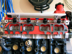
I contacted Manj, and we quickly determined that the insulator I received had
somehow been machined incorrectly. The port openings were too large by about Ľ".
Manj quickly sent out a replacement, and the difference was immediately
noticeable:
I painted the new insulator red and prepared to install it. |
|
| |
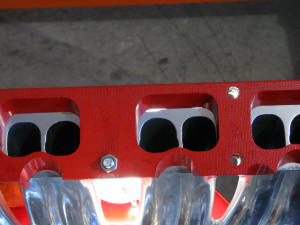
First came the intake gasket. Although Manj stated that I could get away with no
gasket on a first-time installation, I already had the gaskets, so I decided to
use them:
|
|
| |
Next came the insulator plate:
|
|
| |
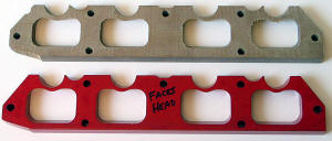
I modified the gasket that fit against the manifold to eliminate the center ribs
that weren't needed anymore:
|
|
| |
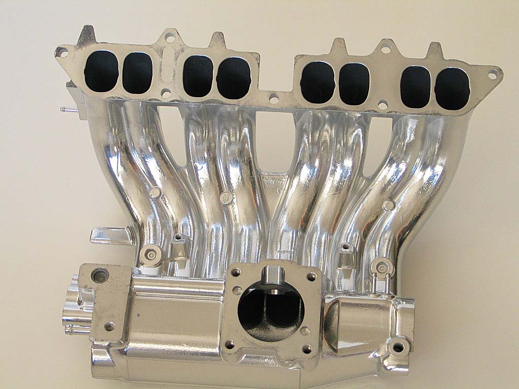
Once the injectors, fuel rail, and TVIS eliminator were in place, I could install the intake
manifold. I'd had the stock unit
Extrude-Honed, and then I'd had it ceramic coated, as the stock finish was pretty
awful:
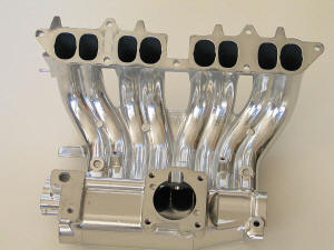
I considered an aftermarket manifold, but most of those flow a
LOT of air, and I felt they would hamper drivability. Well, I'll soon
find out if sticking with a modified stock manifold hampers power production too much.
|
|
| |
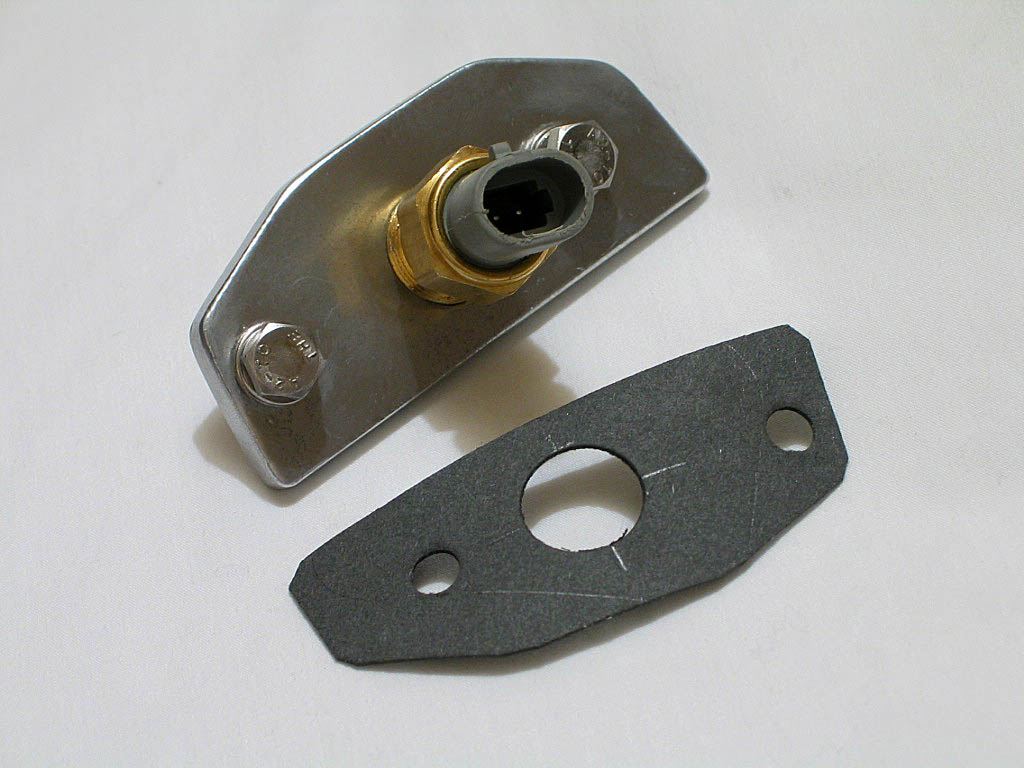
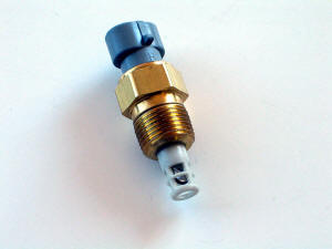
Before the intake could go into position, however, I needed a bracket for
the TECł Manifold Air Temperature (MAT) sensor:
|
|
| |
I decided to
fabricate an aluminum plate that would position the MAT sensor where the
OEM cold-start injector normally fits, right up under the throttle body mount.
Nothing fancy, as I don't have much in the way of metalworking tools
beyond a hacksaw, a drill, and a grinder, but this was a pretty
simple task. I used a small piece of Ľ" stock, and here's the result:

I also cut a gasket at the same time.
|
|
| |
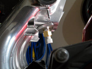
I installed the plate and the sensor:
|
|
| |
I slipped the manifold onto the three M8 studs, and loosely tightened
them to keep the manifold from rocking.
|
|
| |
Continued on next page... |
|
|
|
|
|
Back to Start
Page
1
2 3 4 5
6
7
8
|
|
|
|
|
|
|
|
|
|
|