|
Last Updated
23 June, 2005
|
|
|
Back to Start
Page
 1
2 3 4 5
6
7
8
9
10
1
2 3 4 5
6
7
8
9
10
 |
|
|
UNDER CONSTRUCTION
Installing the 3SGTE
|
|
| |
I'd purchased a remote oil filter kit, as
described here.
I needed to find a location for the remote filter housing that was easily
accessible during oil changes. I also needed to fabricate oil lines to
reach it and ensure they provided enough slack to remove the filter.
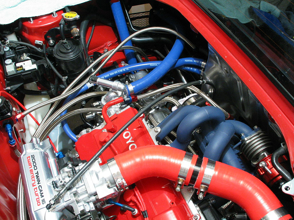
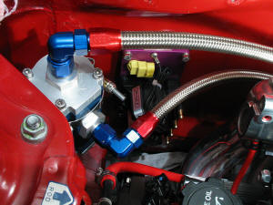
I decided to locate the filter housing in the right-rear corner of the
engine bay:
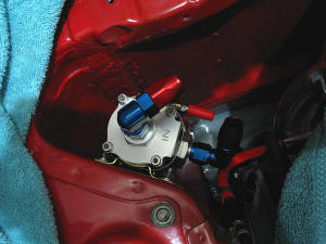
To perform a filter change, a T-bolt clamp is loosened, and the housing is
lifted clear of the mount. I can then turn it upside down to drain the oil
out, then remove the housing cover to replace the filter element.
The hoses to the remote oil filter adapter will be long, looping around
the left side of the motor and then back to the adapter. This provides
slack for lifting out the filter.
|
|
| |
The adapter housing has ˝"-NPT holes. I used
Earl's swivel hose ends for these connections.

|
|
| |
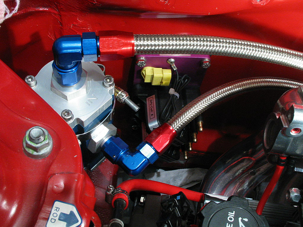
The filter housing uses -10 AN O-ring fittings, so I needed reducing
adapters to bring the size down to -8 AN flares. I then used 90ş hose
ends:
|
|
| |
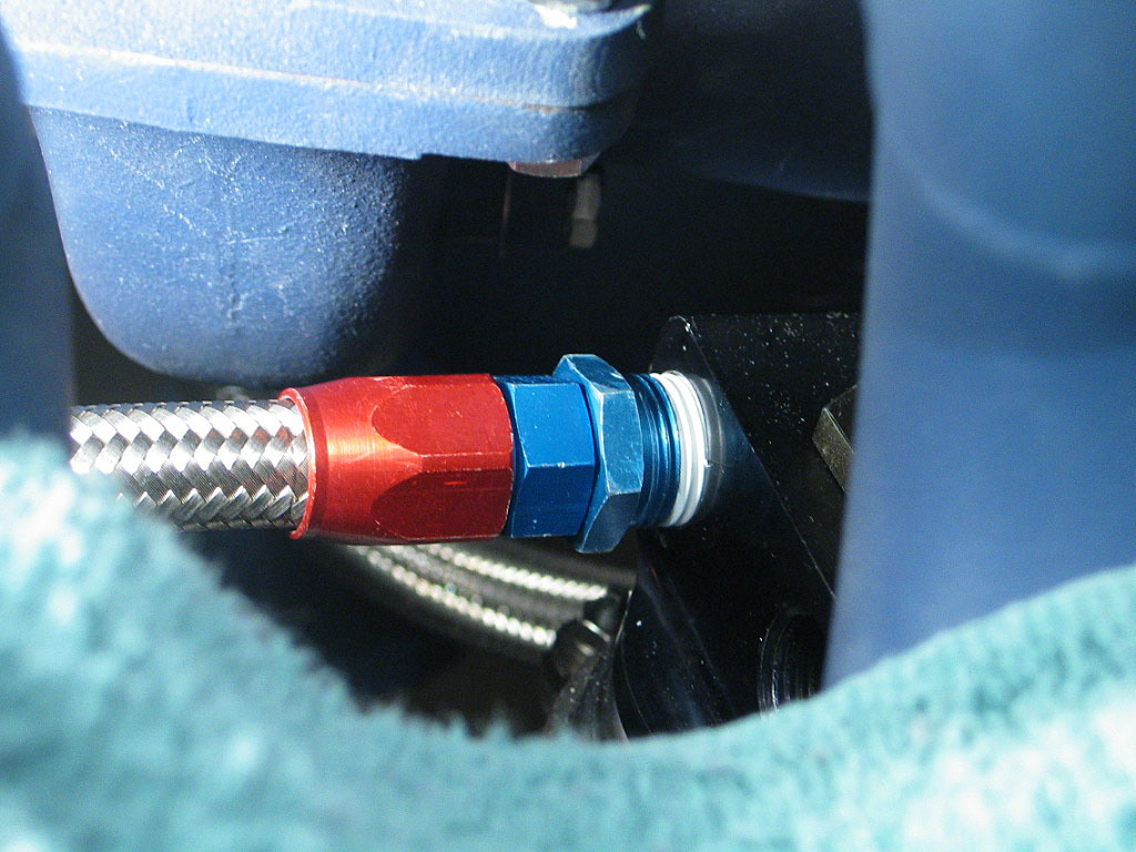
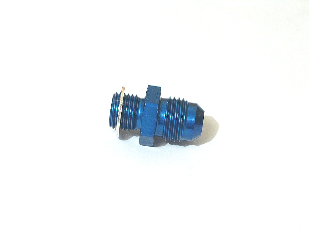
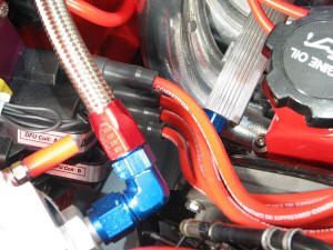
Next came the fuel plumbing. The fuel filter
typically uses a banjo fitting, but I was using a metric-to-AN adapter:
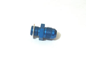
The fuel filter takes an M12 x 1.25 thread with a crush washer. The other side is
a -6 AN male flare fitting to accept an AN hose end.
|
|
| |
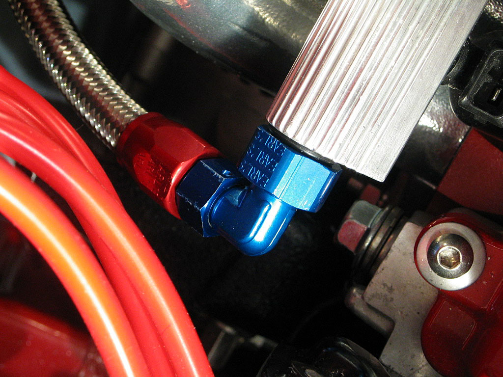
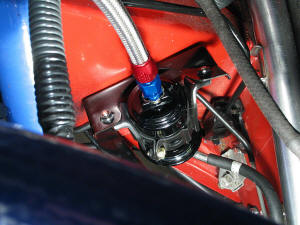
Here's a photo of the fuel line connected to
the filter:
|
|
| |
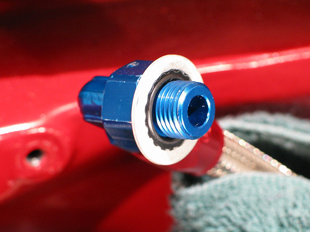
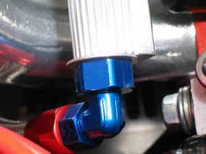
The fuel rail sported -6 AN female threads,
which were beveled, or cupped, at the opening. I thought the cupping would
be adequate to use an O-ring fitting:

However, as you can see in the photo above, the O-ring on the fuel inlet
hose fitting is being forced out to the edge of the fitting. This is bad,
unless fuel being sprayed over a hot engine is your idea of fun.
|
|
| |
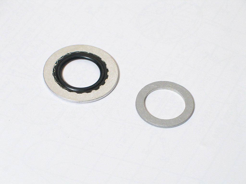
I decided to replace the O-rings with
Stat-O-Seal sealing washers. These consist of a synthetic rubber (usually
Buna-N)bonded to an aluminum crush washer. In theory, this provides the
rubber seal around the body of the fitting, plus the seal of a crush
washer between the two mating surfaces. Hear's a comparison:
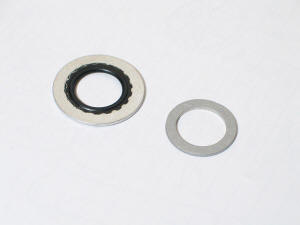
The washer on the right is a -6 AN aluminum crush washer. The washer on
the left is a -6 AN Stat-O-Seal washer. The Stat-O-Seal is quite a bit
larger in diameter, so the inner rubber seal must do the job.
|
|
| |
I installed the Stat-O-Seal on the hose
end...

...then I attached the hose end to the fuel rail:
I'll need to pressure test the fuel system anyway, so we'll see if this
works. If not, I'll just use the crush washer.
|
|
| |
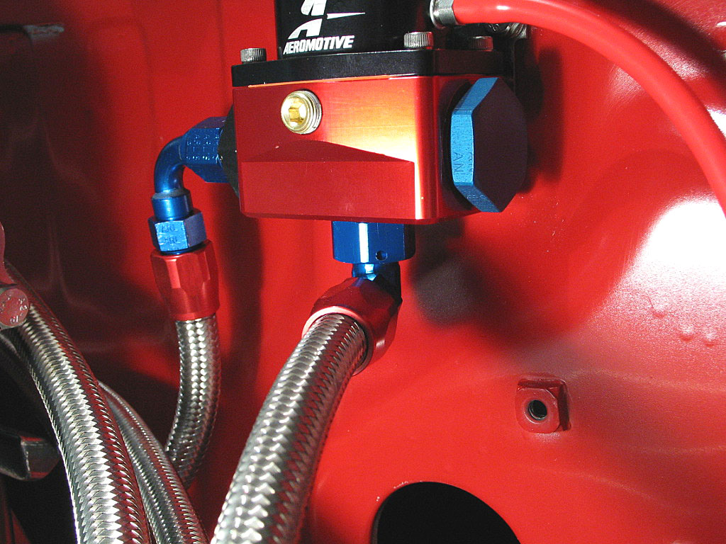
The other end of fuel rail is identical to
the inlet. I fabricated a short length of hose to connect the fuel rail
outlet port to the inlet port of the Aeromotive fuel pressure regulator,
which I'd mounted to the trunk firewall:
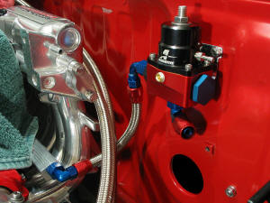
The Aeromotive APR uses huge -10 AN ports, so a reducing adapter was
required,
then the 90ş -6 AN hose end would thread onto the adapter.
The hose has some slack for engine movement, and the swivel hose end helps
alleviate stress on the hose as well.
|
|
| |
The outlet port on the bottom of the APR
calls for a -6 AN O-ring fitting, which feeds the fuel back to the tank:
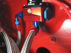
The other end of the fuel return line is simply a clamp-on fitting to the
return tube.
This completes the fuel line plumbing.
|
|
| |
One of the benefits of eliminating the cruise
control is simplifying and shortening the throttle cable arrangement. In
the stock configuration, the cable goes from the pedal to the cruise
control "carousel", wraps around a drum that transfers the motion to
another cable, changing direction 90ş. The second cable heads for the
throttle body, where it makes another 90ş turn to reach the throttle
shaft. Not exactly a direct route. I had done some rough measuring, and I was
pretty sure the cable from the pedal would reach directly to the throttle
body if it was re-routed.
First, the cable needs to be pulled back all the way to where it exits the
cabin. Route it down the left side of the fuel tank, then up into the
engine compartment near the shifter cables. I chose to bring it up over
the turbo intake tube and directly to the
throttle body:

Unfortunately, that's where I ran into trouble.
|
|
| |
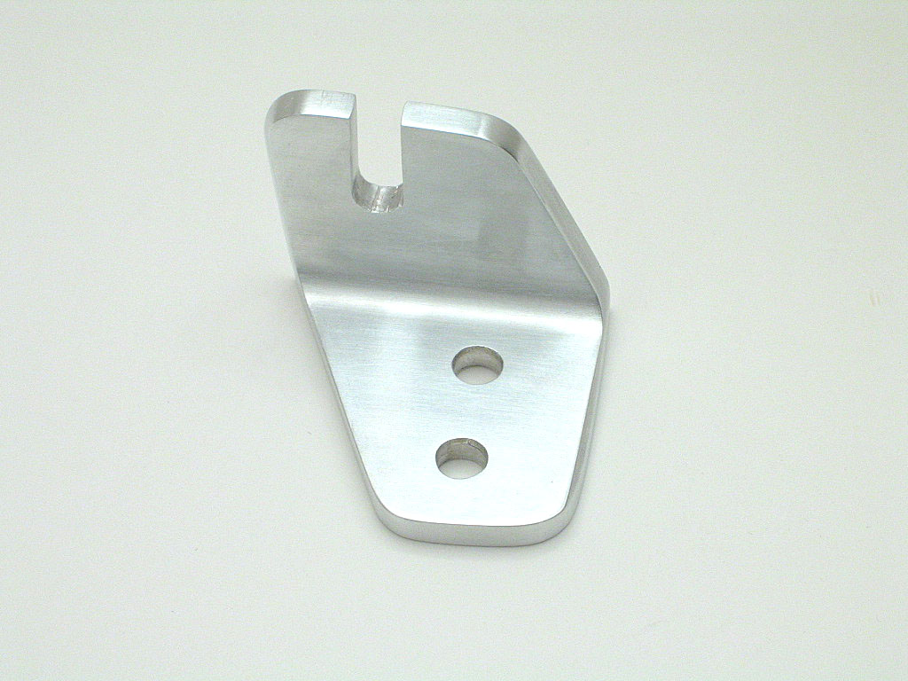
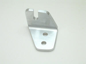
This section of cable is designed to connect to the cruise control
mechanism, not directly to the throttle body bracket. The exposed length of cable
and the threaded adjusting sleeve are both a bit too short to work with the stock
anchor bracket. As a result, I had to fabricate a new bracket. This
isn't a complicated bracket, but my assortment of metalworking tools is
limited to a cordless drill, a hacksaw, and some grinding tools.
Luckily, I had some Ľ" thick, 2" aluminum angle stock from
Online Metals that did the job, but it took me several hours to come up with the finished
piece:
|
|
| |
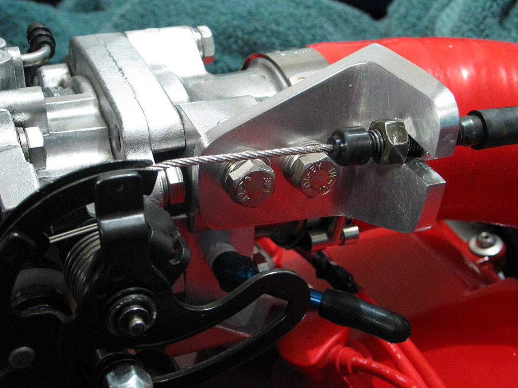
I installed the bracket...
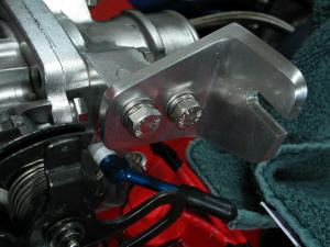
...then attached and secured the cable:

I checked the action to be sure the throttle opened smoothly and fully.
|
|
| |
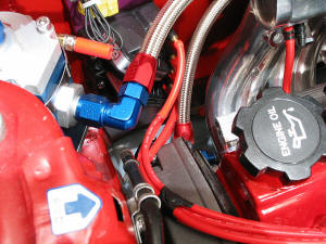
Custom spark plug wires needed to be
sized and ordered, but I needed to find a home for the TECł direct-fire unit (DFU)
first. I wanted a location that was fairly cool, yet close to the engine.
I decided to mount it next to the remote oil filter housing, on the trunk
firewall:
|
|
| |
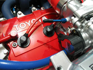
I was going with
Magnecor KV-85
wires, as I'd had success with them before. In order to get accurate
lengths, I used an old set of stock wires with the distributor connectors
cut off. I slipped some vacuum hose over the bare ends, and ran them back to the DFU.
This enabled me to route the wires exactly where I wished, and simulated the
actual wire runs.
|
|
| |
Here's a plug for
ApexPerformance.net. Linda at Apex
handled my order flawlessly, and their price was below that quoted by
anyone else. The wires were assembled and shipped direct from Magnecor. I will definitely
buy from them in the future:
I could have been a bit more exact on the measurements, but it was nothing
major.
|
|
| |
I still had many components that needed to be mounted. Next on my list was
the Idle Air Control Valve (IACV).
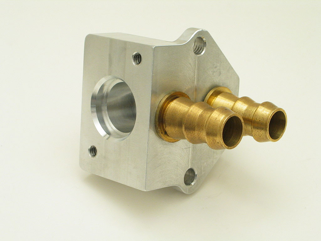
The IACV I purchased to work with the TECł was a universal type. It appears
that it was meant to be mounted through a panel or firewall. Here's a
photo of the IACV body:

The solenoid valve mounts into the large hole on the left of the body. The
hose connections are ˝" O.D. One runs to the throttle body and the other
to the intake pipe (pre-turbo), to provide a supply of air.
|
|
| |
The design of this IACV made it difficult to
mount, as I needed access to the front and the back of the unit. I also needed a bracket that would mount it
securely, in a location where running the hoses wouldn't be a big problem.
I finally decided to make a simple flat mounting plate that attached to
the cylinder head in the same location as the EGR blockoff plate:
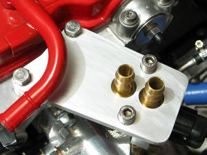
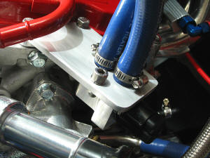
This bracket made it simple to attach the air hoses and electrical
connector:
|
|
| |
Continued on next page... |
|
|
|
|
|
Back to Start
Page
1
2 3 4 5
6
7
8
9
10
|
|
|
|
|