|
Last Updated
07 April, 2005
|
|
|
Back to Start
Page
 1
2 3
4 5
6
7
8
9
10
1
2 3
4 5
6
7
8
9
10
 |
|
|
UNDER CONSTRUCTION
Installing the 3SGTE
|
|
| |
Like the
Rebuild section, the following pages do not describe the process for
installing a stock (or relatively stock) 3S-GTE motor. Many of the stock
components have been entirely replaced on this motor, such as the turbo
system, wiring, ignition, ECU, etc.
If you are looking to install a mostly stock 3S-GTE, then
the best course might be reversing the steps in the
Removal section.
One of the biggest challenges for this project was finding mounting
locations for all of the aftermarket components. Adding a few things like
a catch can, BOV, etc., isn't too much trouble on a basically stock motor.
However, I had to find a home for about ten new pieces, and that proved
difficult.
The other major issue was fabricating an intake plumbing
system from scratch. This is a challenge, as a trial-and-error approach can
ruin your wallet.
|
|
| |
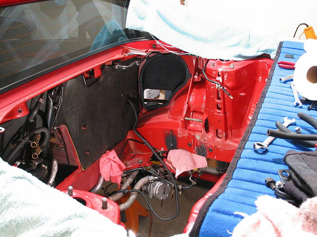
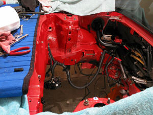
With the motor out, I removed the
intercooler, which I was replacing with my Greddy unit. I also removed the
clutch slave cylinder, as I was replacing the stock hose with an SS hose from Club MR2.
I removed the other accessories and took the time to clean the engine bay.
There were some areas where the paint had chipped off the sealant, and
others where some type of black paint or undercoating had been applied,
but otherwise it was clean:
|
|
| |
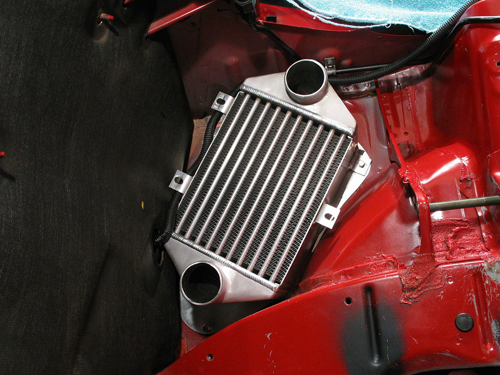
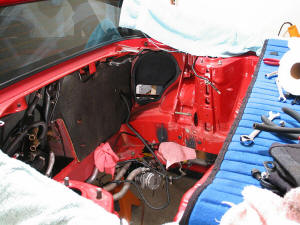
I installed the Greddy intercooler from my
previous MR2. First an adapter panel is placed in the opening, as there is
no duct between the I/C and the body as in the OEM install. Then the I/C
is installed using two of the original mounting locations:

|
|
| |
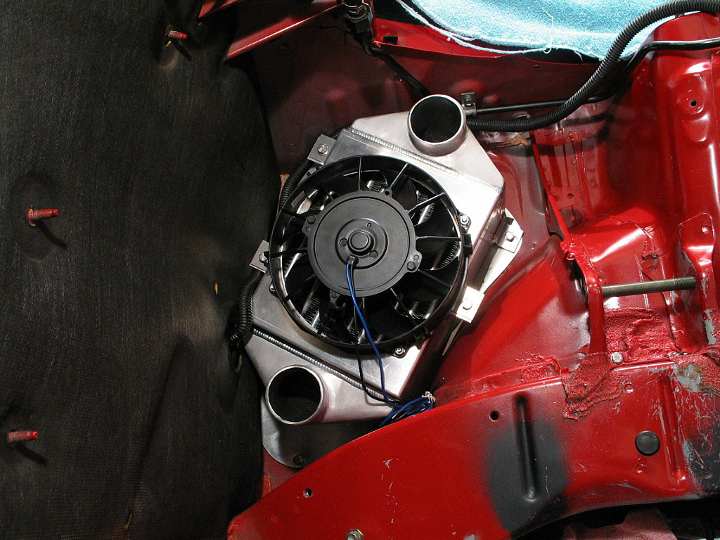
Once the I/C is in place, the stainless fan
shroud is installed, with the fan already in place:
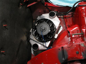
NOTE: The Greddy intercooler kit includes neither the fan shroud nor the fan.
I got my shroud from Manjit Gosal and my fan from Tripac.
|
|
| |
After getting the sludge out of the coolant
overflow tank (coffee pot cleaner works well), I reinstalled it, using the three 12mm bolts on the lower
mount points:
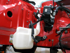
The upper mount was left unattached for now.
|
|
| |
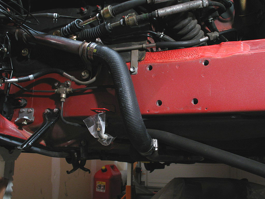
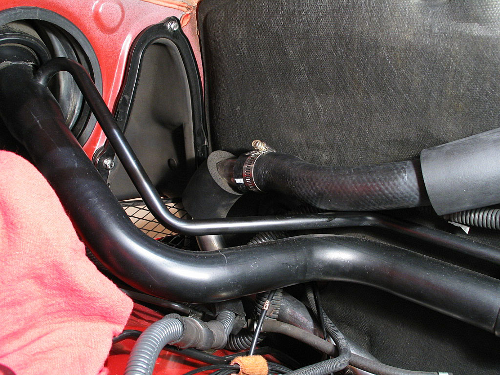
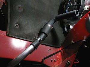
Three radiator hoses were getting replaced
while I had such easy access within the engine bay. Toyota calls them
Radiator Hose No. 1 or Inlet (16571-74140), No. 6 (16576-74010), and No. 7
(16558-74010).
Hose No. 6 connects two sections of stainless pipe:

Some soapy water always helps with installing the hose in the proper
alignment.
|
|
| |
Hose No. 1, also called the Inlet hose,
connects one of the long coolant tubes under the car to the water pump
inlet manifold. Since the motor was still out, I simply slipped the end of
the hose onto the pipe without tightening the clamp. I'd snug it down
after the other end was attached:
|
|
| |
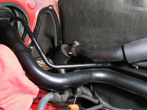
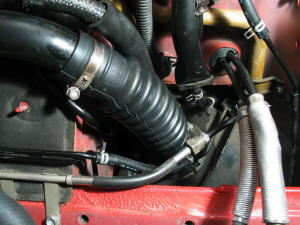
Hose No. 7 runs from a stainless "J" shaped
tube to the coolant outlet manifold. I slid
one end of the hose onto the pipe, aligning the the painted stripe with the
paint mark
on the tube:
|
|
| |
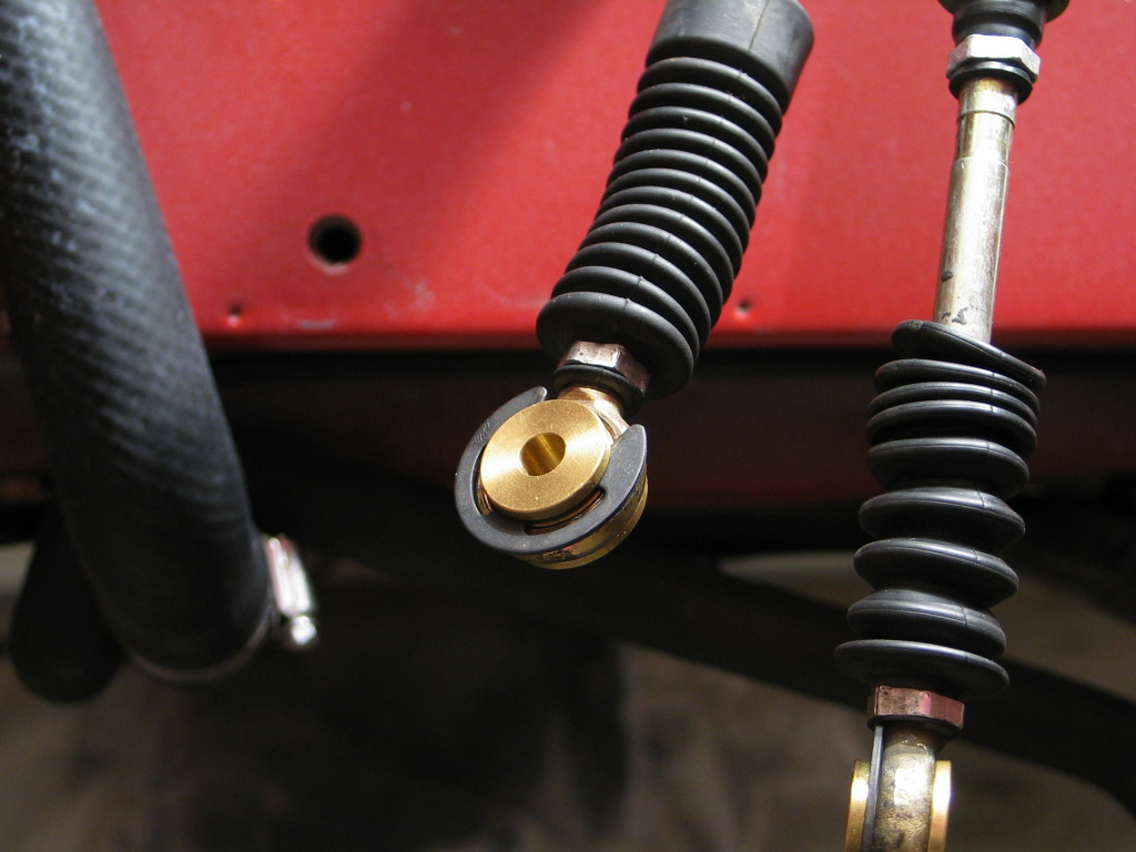
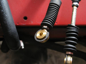
I'd purchased brass shift cable bushings
from Club MR2. Hopefully these would
change the shifter action to something a bit more precise. The stock
bushings are very squishy.
The new bushings are easy to install. Simply push the OEM bushings out with a
screwdriver, then install the brass inserts and attach the "E" clip:
|
|
| |
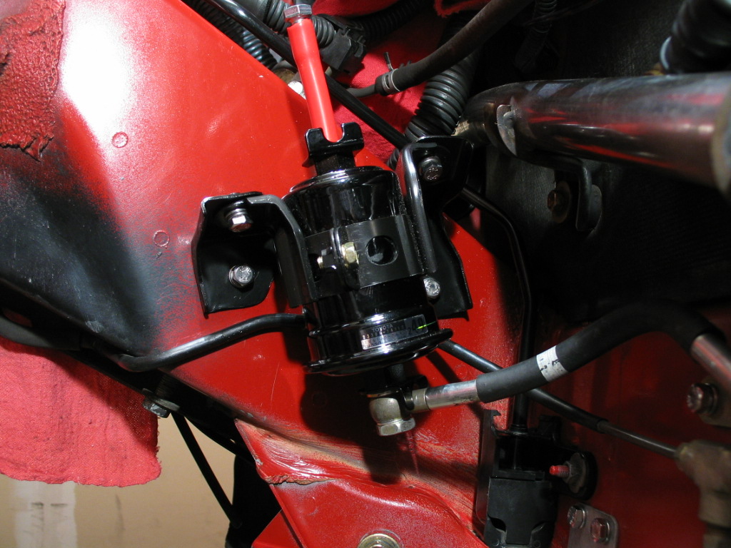
I installed a new fuel filter, and new crush
washers on the lower banjo bolt.
The top fitting was getting converted to aircraft SS hose, so I simply
plugged it with a short length of silicone hose for now:

|
|
| |
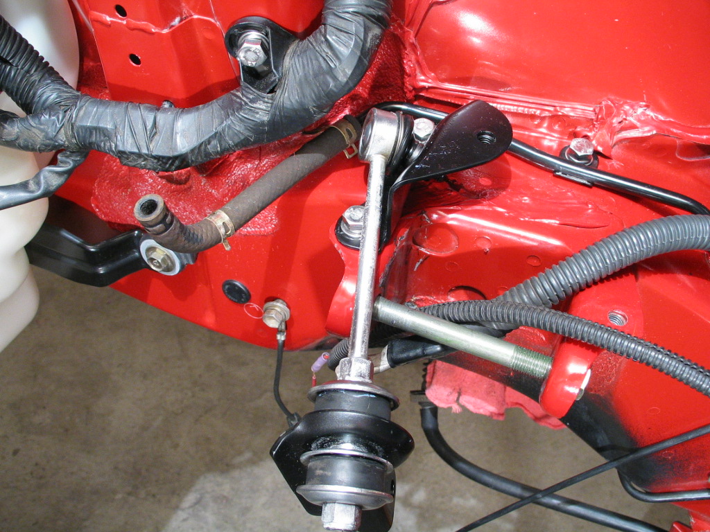
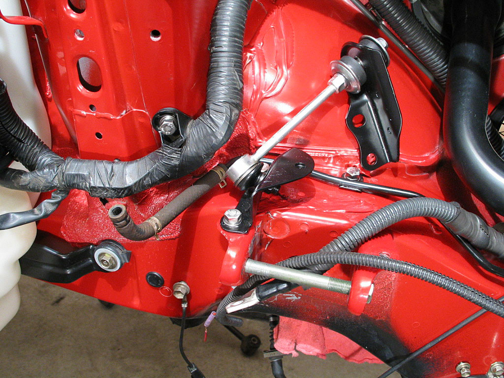
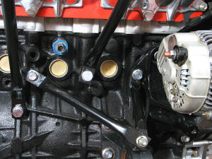
Next, I installed the two bolts that mount
the lateral control rod,
which is located just above the left-hand engine mount plate:
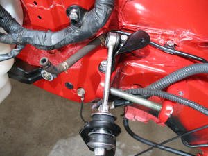
Rotate the rod up against the inner wheel housing to keep it out of the
way for now:
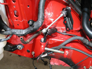
The other end will eventually attach to the left-hand engine isolator.
|
|
| |
I had replaced the stock fuel pump with a
Supra Twin turbo pump, as access to the fuel tank was a bit easier with
the motor out. The main fuel filler hose had to be cut off, so I went
ahead and replaced all of the tank hoses:
As you can see, most of them are just �" I.D. fuel hose.
|
|
| |
I removed the driveshaft bearing support
from the old motor and attached it to the new motor:
The support is aligned by two dowels. I applied some thread lock to the
bolts and torqued them to BGB specs.
|
|
| |
Next comes a short brace from the bearing
support to the alternator bracket:
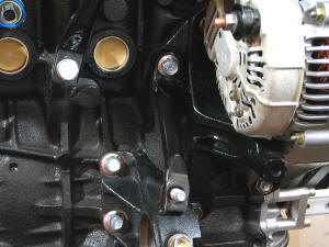
Note that this brace is very similar in size and shape to the engine
mounting stay. However, it is beefier (feels like solid rod, not tubing) and the end that attaches to the
alternator bracket is rounded to fit the cutout on the bracket.
|
|
| |
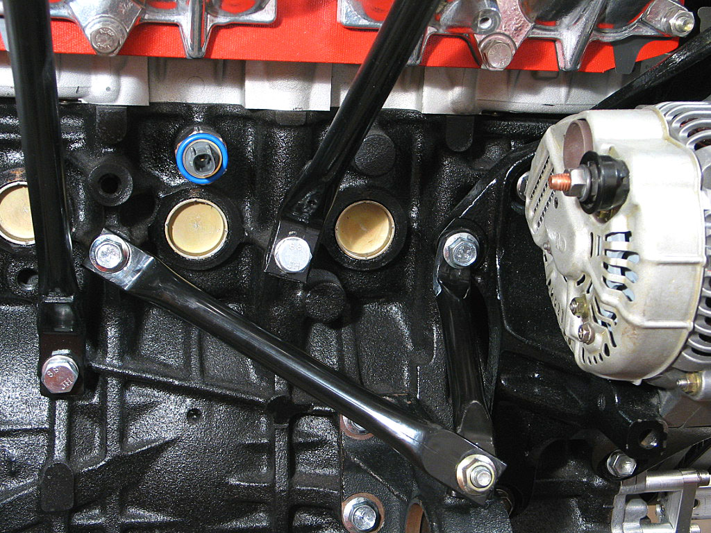
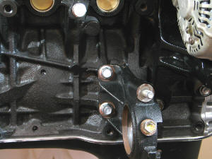
There's one more brace, a longer one that
attaches to the engine block:
With both braces in place, I applied some thread lock and torqued them to
specs.
|
|
| |
I attached the motor to the hoist and
detached it from the engine stand. I used a piece of 1" wooden dowel as a
clutch alignment tool. I found that if you tap it into the engine block
with a rubber mallet, it will stay in place during the assembly.
With the dowel in place, I slid the clutch disc on, with the "flat" side
facing the flywheel and the raised hub section facing out towards the
pressure plate. I then installed the pressure plate, which had been
balanced as part of the crank & flywheel assembly:
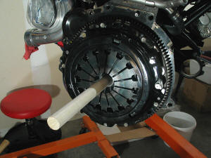
While keeping the dowel centered in the opening, I evenly tightened down
the six bolts, and torqued them to spec.
|
|
| |
With the clutch installed, I lowered the
motor onto a mechanic's creeper. Now I needed to attach the transmission,
which was also on a creeper:
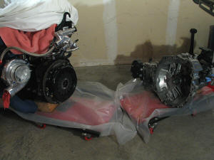
The plastic sheeting on the creepers makes it much easier to reposition
the pieces during assembly.
|
|
| |
I had trouble getting the transmission input
shaft to slide into the clutch, wrangling with it for an hour or so. I
started to think that the clutch, which was an RPS Sport clutch, might
have been the wrong part. I hadn't test fitted the disk onto the input
shaft to be sure.
I had decided to remove the pressure plate and check the fitment when I
noticed that the rubber dust boot that fits over the clutch release lever
was exerting a slight pressure on the lever. As I jostled the transmission
into position against the motor, it had enough springiness to slowly force
the throwout bearing down the input shaft until it was mis-aligned, and
the bearing would jam when the pieces were fitted together.
I removed the dust boot, and the pieces slid together perfectly.
|
|
| |
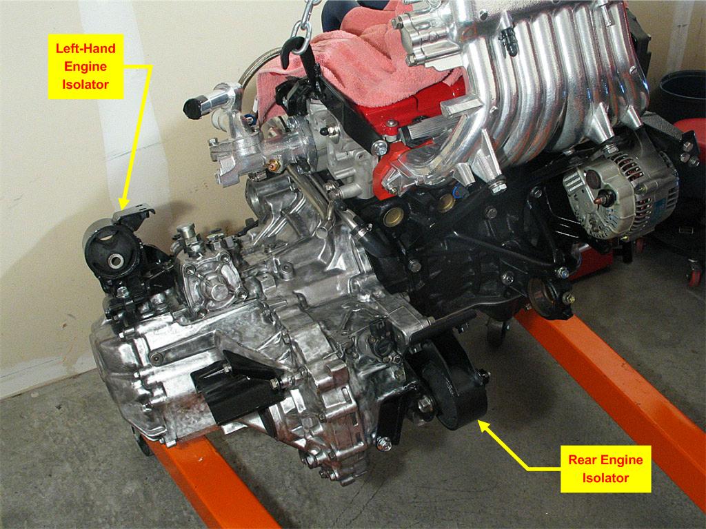
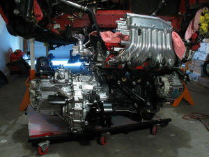
With the engine and trans in place, I
installed the three 17mm mounting bolts, and the two 14mm mounting bolts,
and torqued them to spec with some thread lock. Here is the completed
unit:
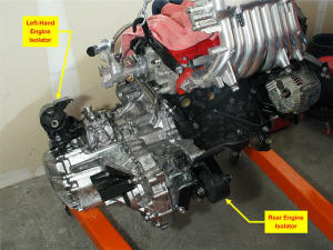
Note that the left-hand isolator (the rubber & steel part of the mounting
assembly) is already attached. Also note that the rear isolator is
attached. You'll need to REMOVE the rear isolator, as it will get in the
way as you raise the motor.
|
|
| |
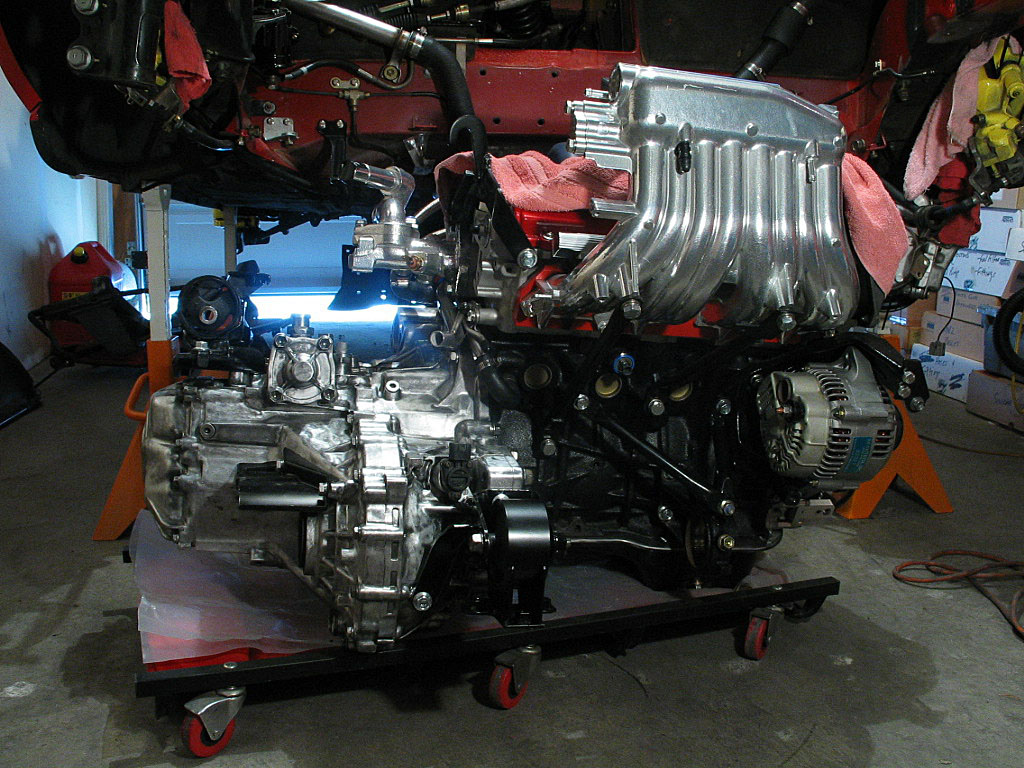
I set the assembly down on a creeper and
wheeled it into position under the engine bay:
|
|
| |
Continued on next page... |
|
|
|
|
|
Back to Start
Page
1
2 3
4 5
6
7
8
9
10
|
|
|
|
|