12 November, 2004
Removing the 3SGTE (continued)
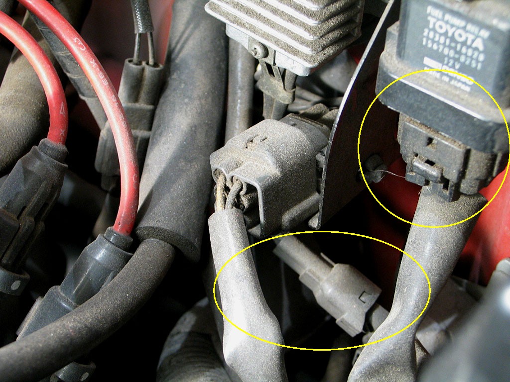
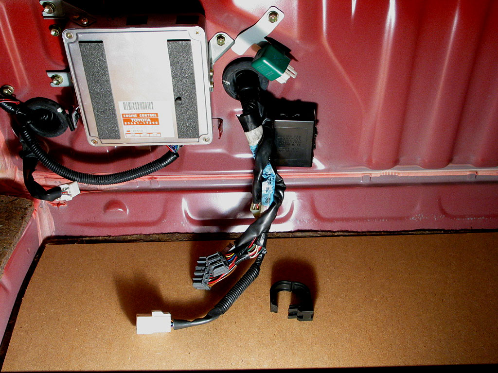
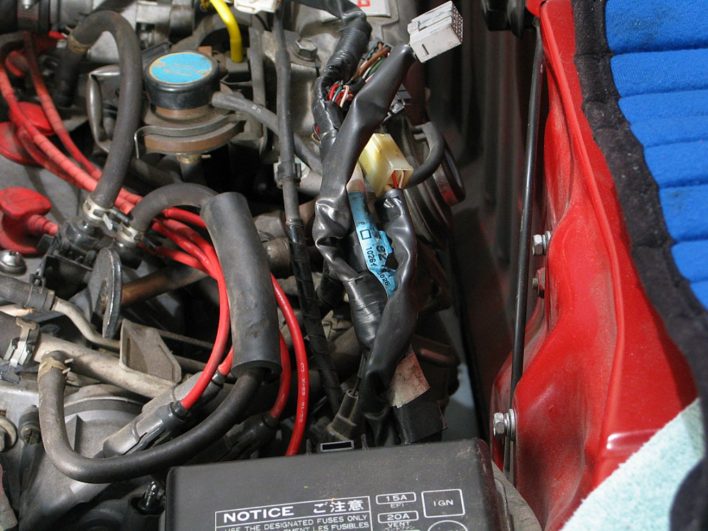
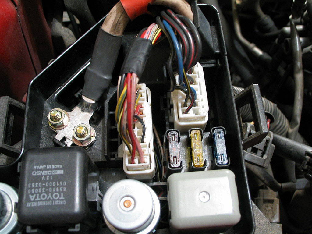
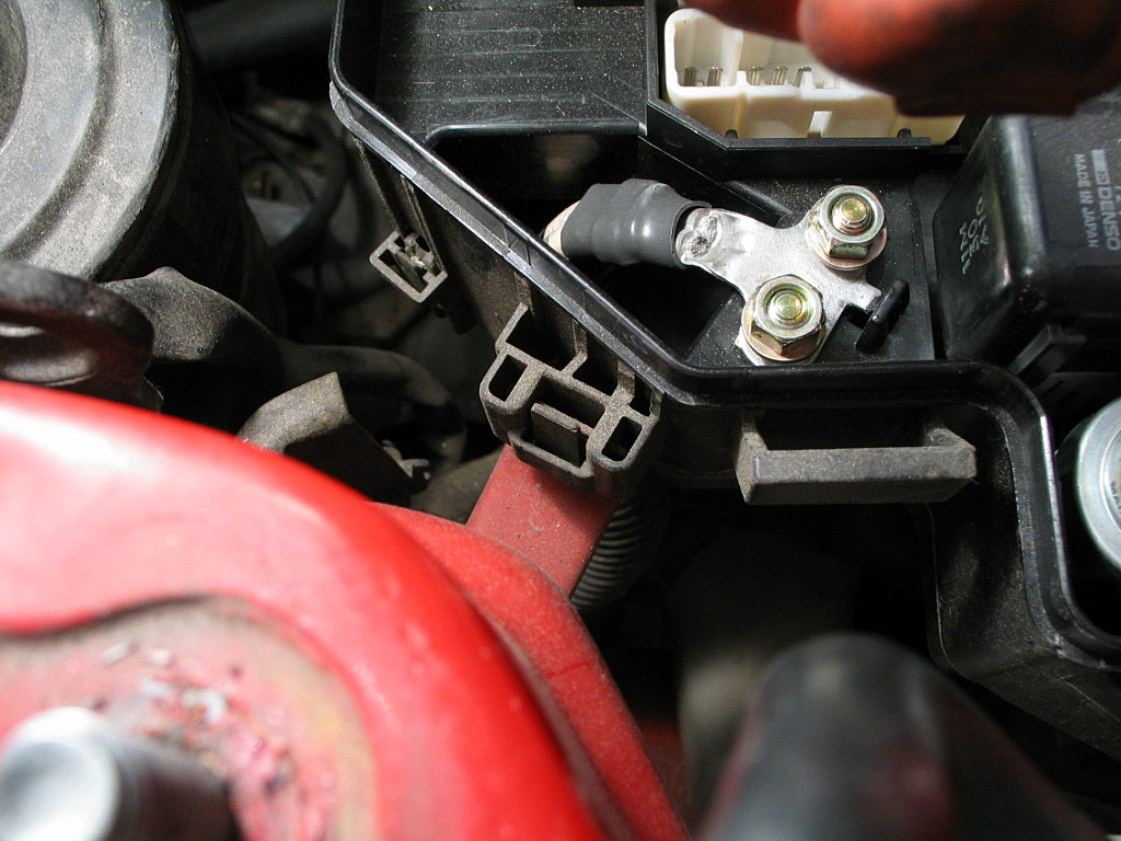
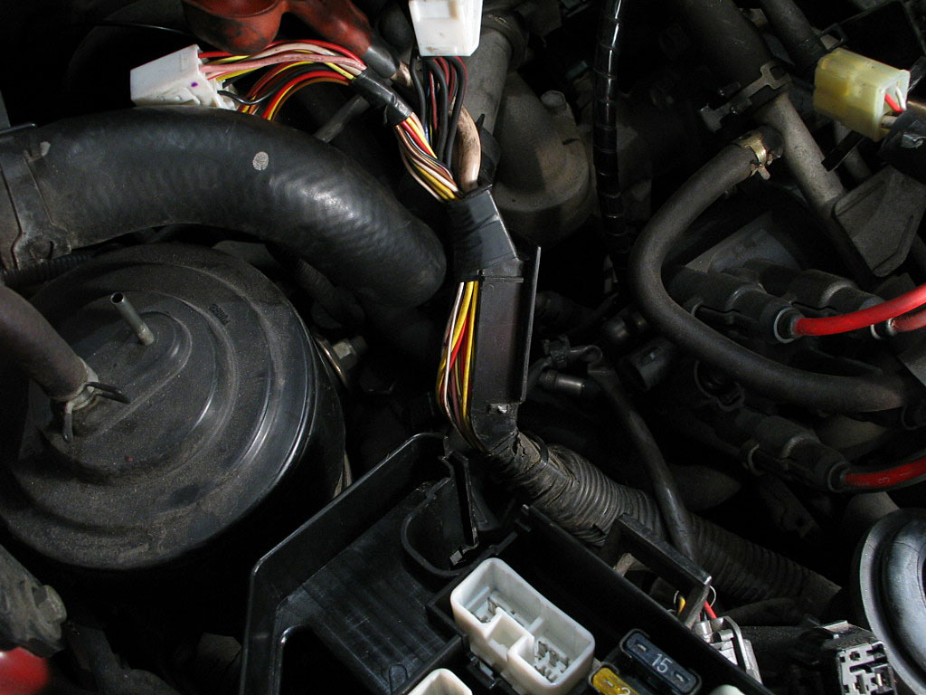
Mounted on the rear firewall is a bracket that secures the fuel pump relay, the fuel pump resistor pack, the solenoid (fuel injector) resistor pack, and the Idle Air Control Valve (IACV):

You only need to detach the connectors to the fuel pump resistor pack and the fuel pump relay, circled in yellow below:
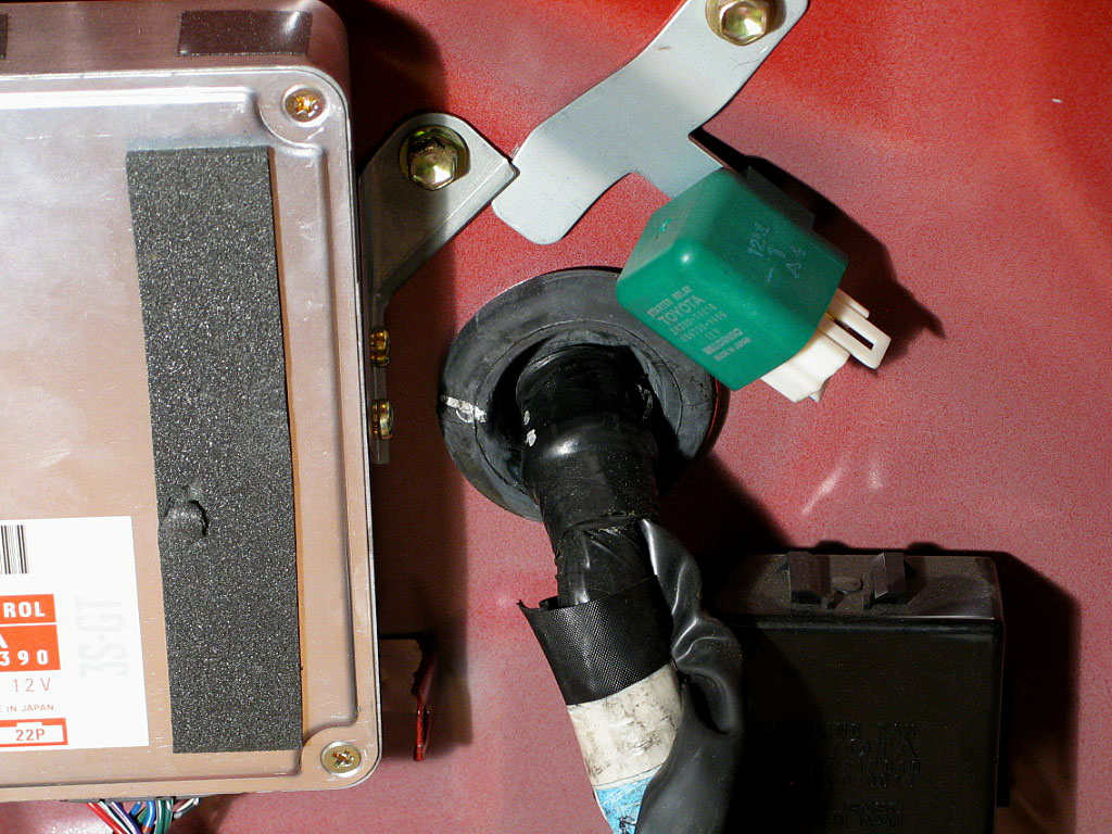
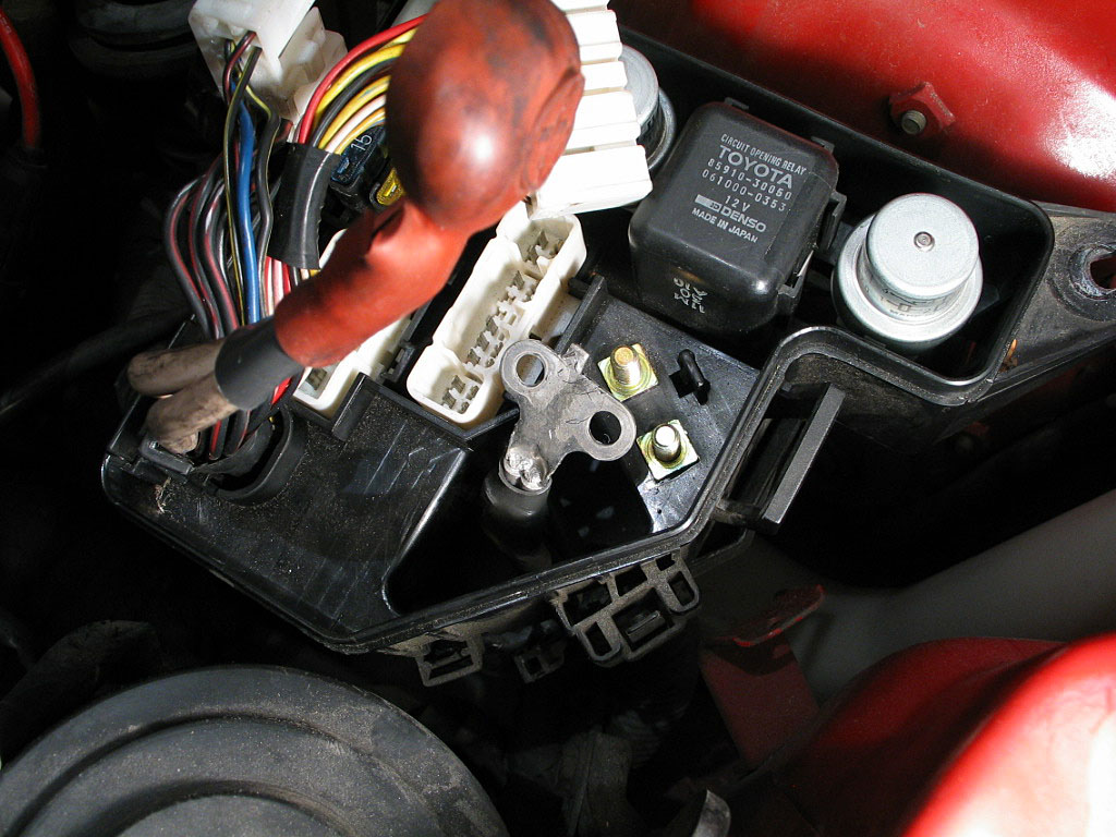
Remove the two 10mm bolts that secure the bracket to the rear firewall, and lay the components on the cylinder head.
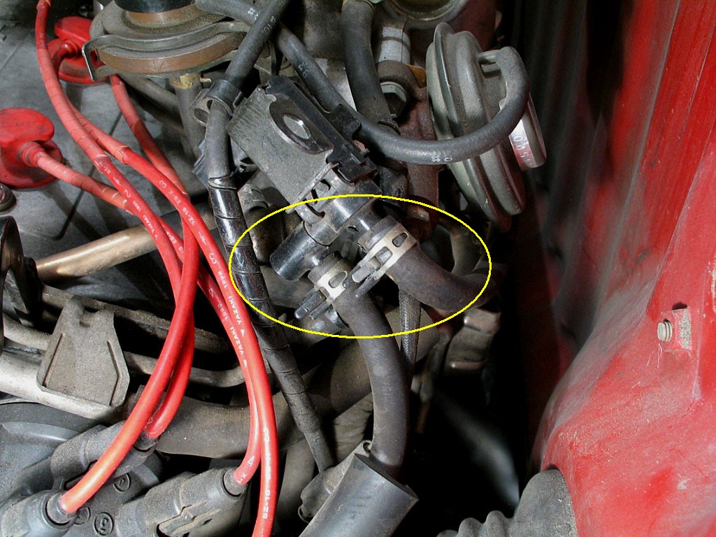
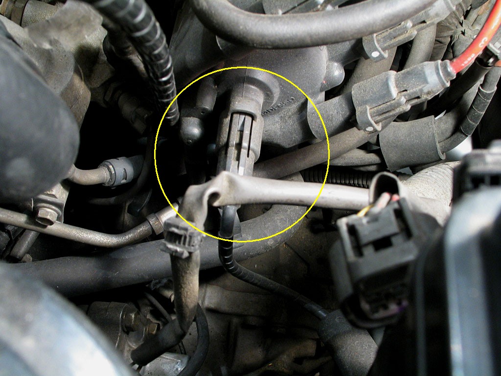
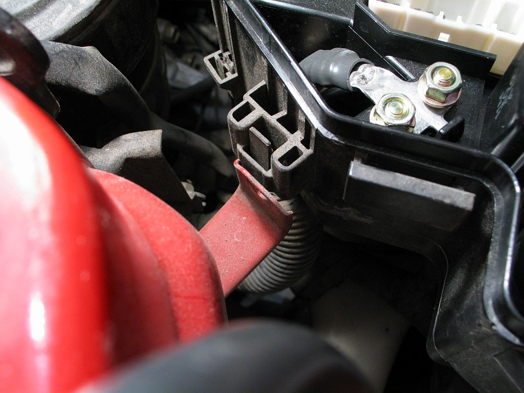
There is not much slack in the hoses, so trace the hose that leads to the back of the intake manifold:

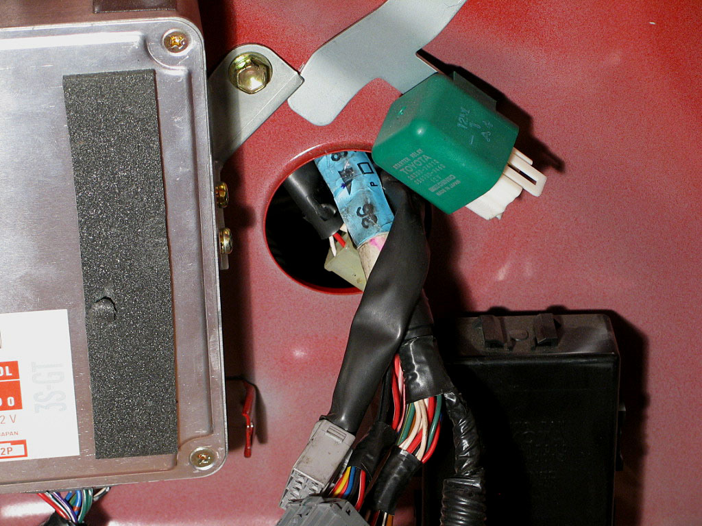
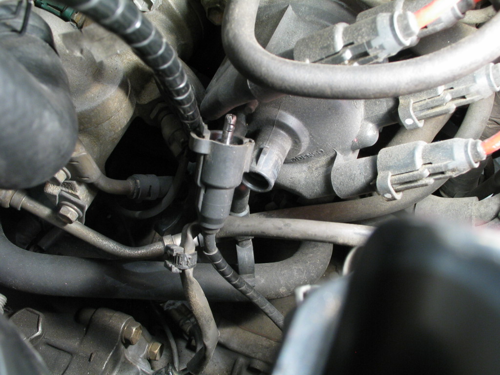
Loosen the clamp on the intake manifold nipple, and slide the hose off. This will give you enough slack to move the IACV out of harm's way. This is safer than trying to remove the hose from the plastic housing of the IACV. It's a pricey part to replace if you damage it.

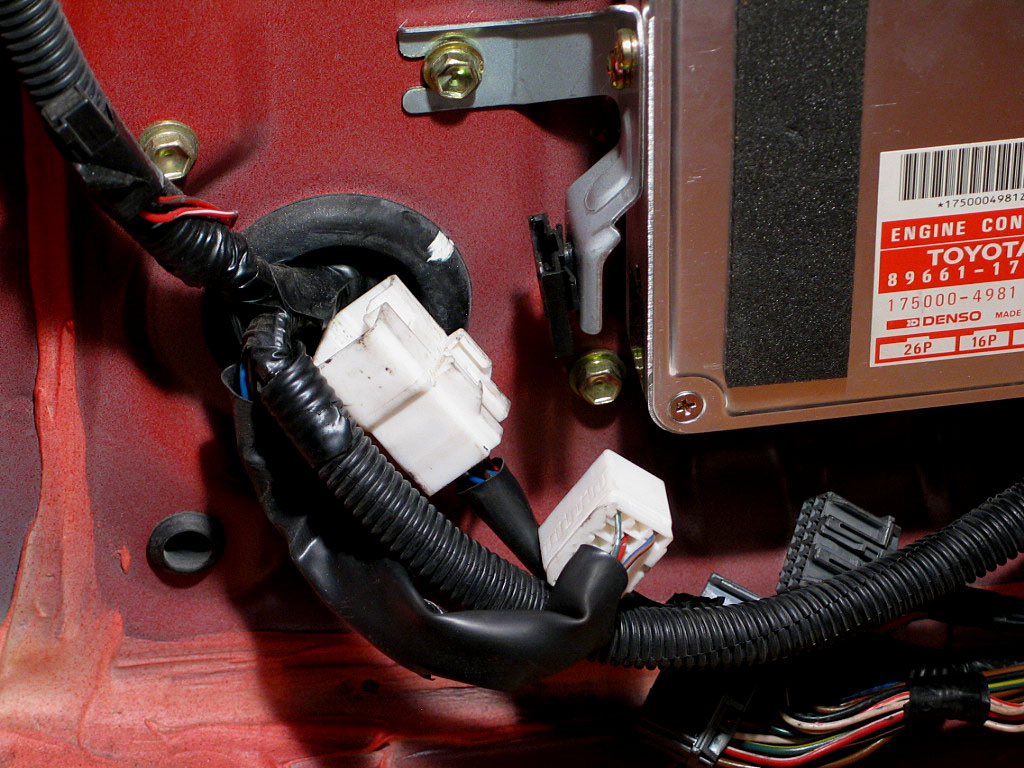
Remove the middle and left-side connectors by pressing in on the locking tab and gently pulling the plugs free. Because there are so many contacts, you'll need to wiggle the connector slightly while pulling.
Leave the right-side connector attached.

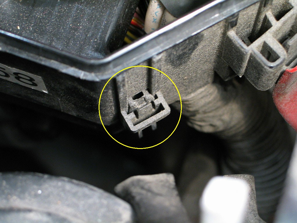
Detach the connector by pressing in on the locking tab, the pulling the connector apart. Slide the captive end of the connector out of its holder:
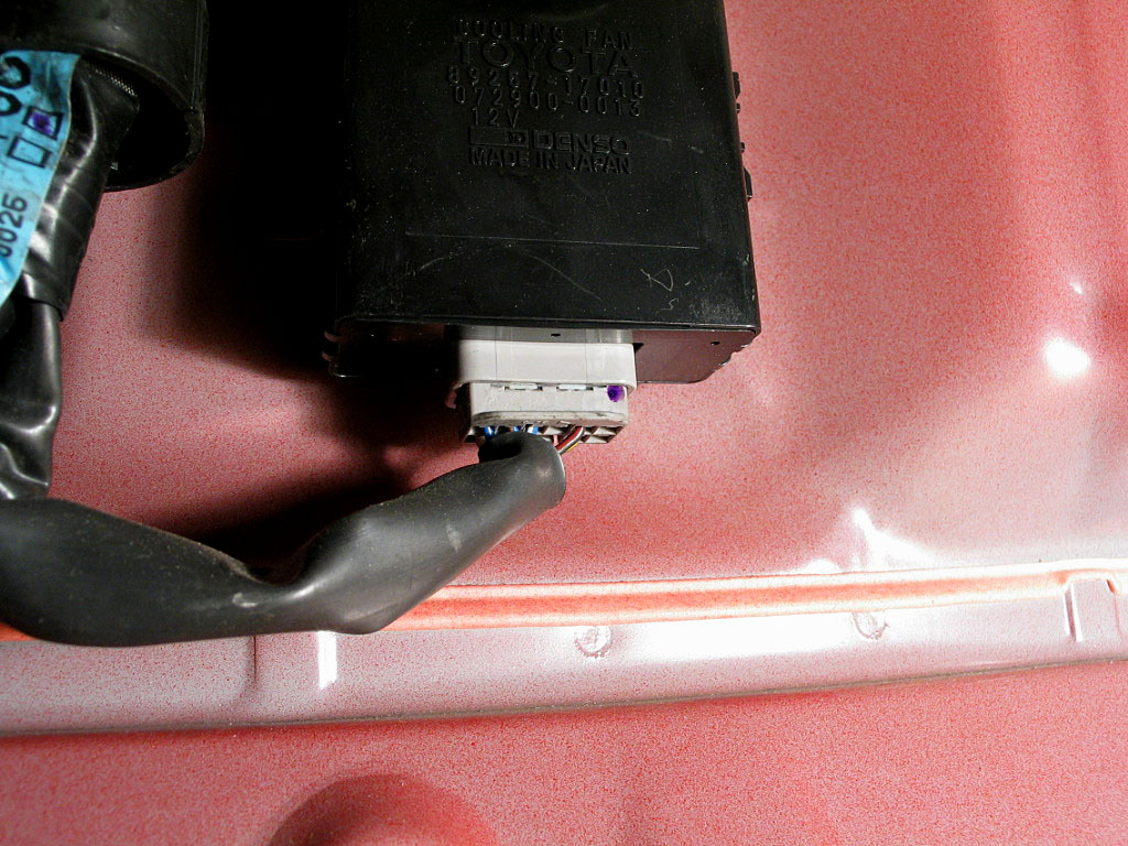
The locking tab is on the back of the connector between the firewall and the ECU. Detach the connector by pressing in on the locking tab and wiggling the plug out.

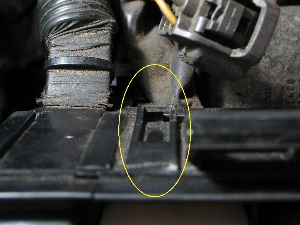
Detach the connector by prying the locking tab out away from the housing and pulling the plug free.
There's a large rubber grommet that seals the hole in the firewall:
Pry the lip of the grommet in towards the hole, and it will pop through. Then you can push the harness through. Be careful, as the lip of the hole has a sharp edge:
And here's the result from the engine bay:
Detach the connector from the cap by prying the locking tab out away from the cap, and pulling on the connector (not the wire). You will probably need to wiggle the connector a bit to free it:
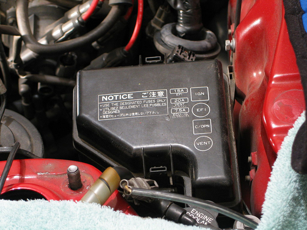
Remove the top cover by pressing in the two locking tabs and lifting off (this one is easy!):
Detach the two white harness connectors by pressing the locking tab in towards the housing, then pulling the connector free.
The case of the fuse box has a locking tab that secures the metal tab on the cable end. Pry out, away from the cable, and the metal tab should spring free, enabling you to remove the cable from the studs:
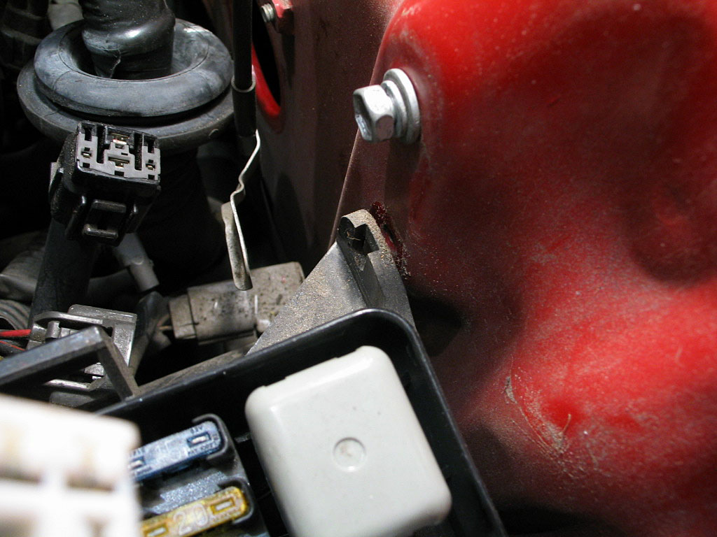
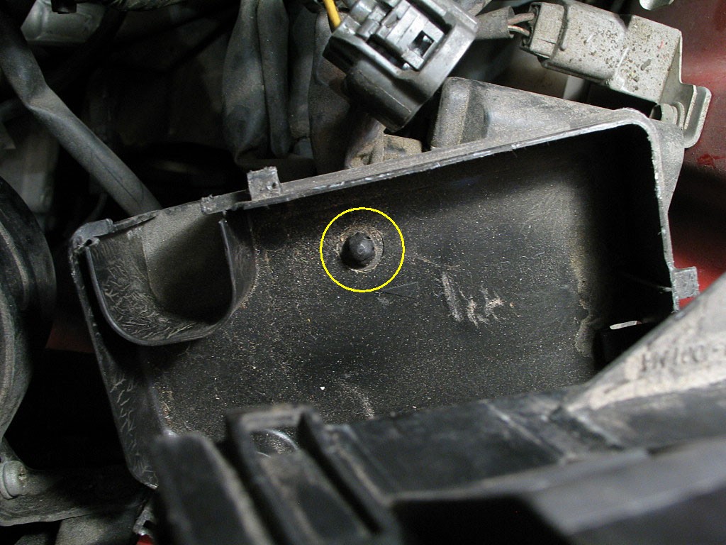
First, detach the box from the car body. Remove the 10mm bolt on the right side of the fuse box that secures the box to the rear firewall:
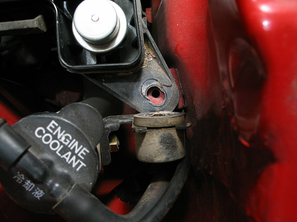
On the other side of the fuse box, you'll need to remove the long 10mm bolt that secures the box to a mounting bracket. Then loosen the 10mm nut that is attached to the coolant reservoir, and rotate the rubber cushion up and away from the fuse box:
There's also a mounting bracket on the strut tower:
Pry the locking tab away from the body of the fuse box far enough to release it, then slide the fuse box up and off the bracket:
You'll note that with the fuse box free of the car body you've only gained a little slack, and there is not much freedom to move it around.


Pry the locking tabs away from the body of the fuse box to release them. The bottom cover needs to be pushed away from the body of the fuse box -- it won't simply drop off.

Unfortunately, this is made more difficult by the position of the locking tabs, which Toyota engineers placed under the box. There are two tabs, one on each side of the sliding sleeve, and they must be pried away from the sleeve.
Basically, you are working blind. I found that if I maintained upward pressure on the harness while trying to release the locking tabs, I was able to free one side, then the other. I pulled the harness up...

...and the sleeve came free:
Just squeeze the locking tabs together and push the clamp through the cover. The cover can now be removed.
At this point, it makes sense to secure all of the loose components to either the motor or the body, to prevent them from get tangled when the motor is lowered out of the car. I used some long cable ties, but anything that is easy to secure would work fine.