03 January, 2005
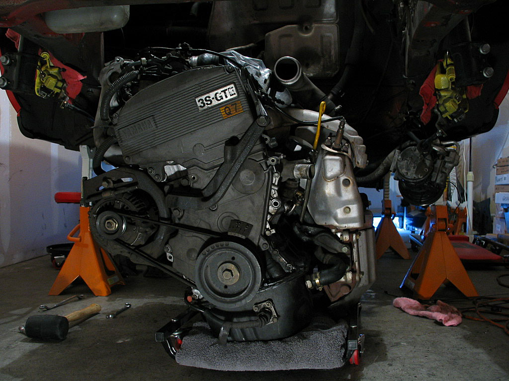
Removing the 3SGTE (continued)
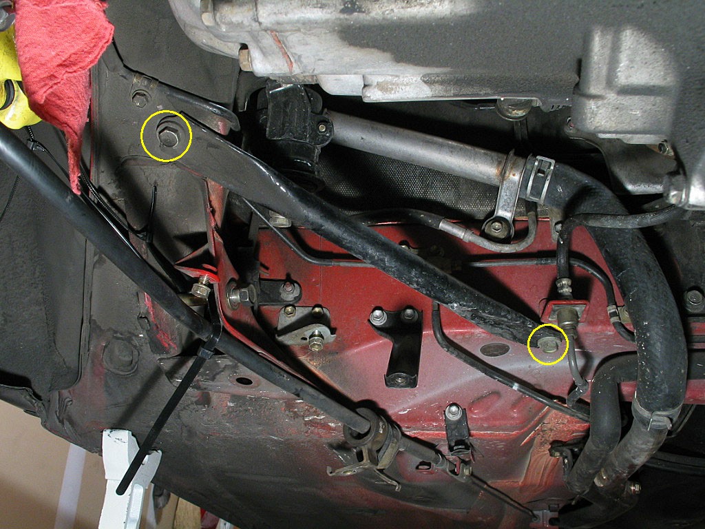
The photo below shows the 14mm bolt securing one end of the right stiffener -- the other end is under the A/C hoses:

Remove both bolts and remove the bar.
Remove the 10mm nut, and rotate the supports down off of the stud.
Remove both bolts and remove the stiffener.
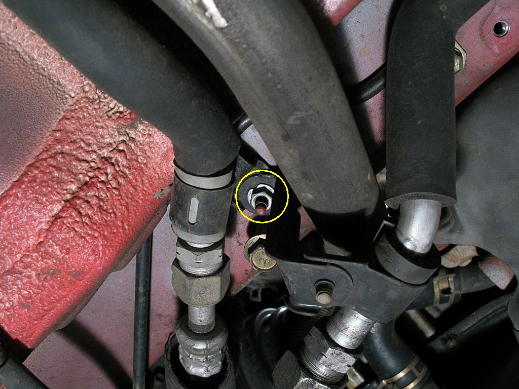
Typically, you would remove the 17mm banjo bolt on the top, and tie the hose end up to the motor. Since I planned to replace the fuel filter as well, I loosened the lower banjo bolt instead:
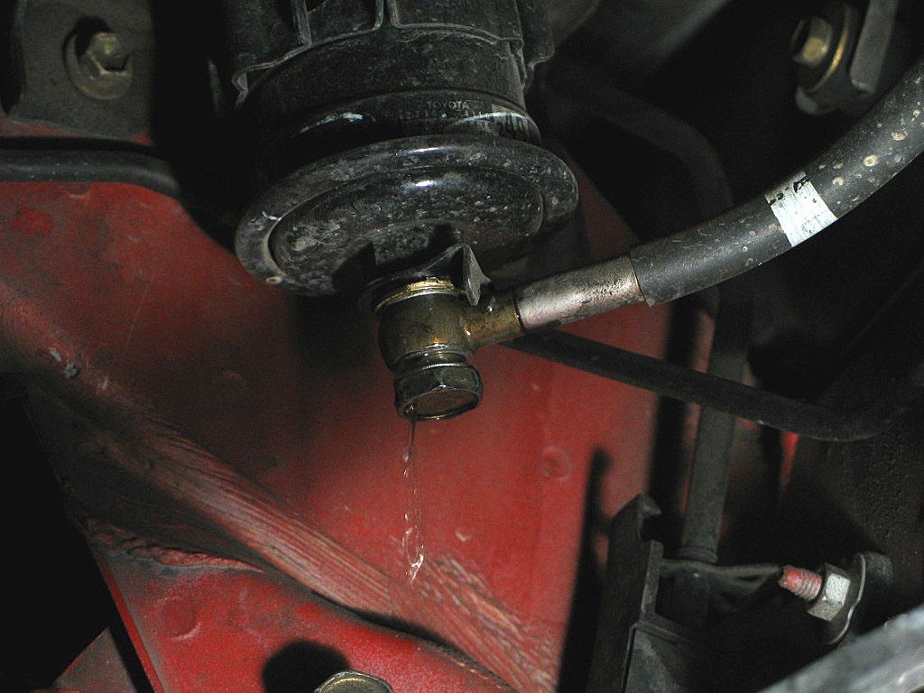
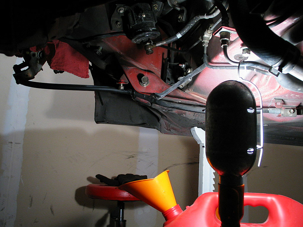
Make sure you catch the fuel that spills out. I placed a gasoline can under the filter and let the gas dribble into the can:
Once the fuel was drained, I removed the fuel filter assembly with the upper hose and tied it to the motor.
It was really difficult to get a photo of the remaining mounting bolts. First, you need to remove the remaining idler pulley bracket bolt. It's located just above the two large pulleys, on the right-hand side (timing-belt side) of the motor:

It's a 12mm bolt and it's very hard to reach. You'll need to experiment with various lengths of sockets and extensions, as the intercooler is very close and vulnerable.
Once you remove this bolt, you can remove the idler pulley bracket from the top of the motor. Do this before continuing.
There's another bolt about 6 inches away. These are both 12mm bolt heads, and they are quite long. Remove them both.
You need to turn the compressor to face the pulley side down, then ease it by the various wires and brackets. Just be sure to keep it fully supported, then you can tie it off to the strut rod mounting bolt where the caliper is tied. Tie it securely, as it is quite heavy:

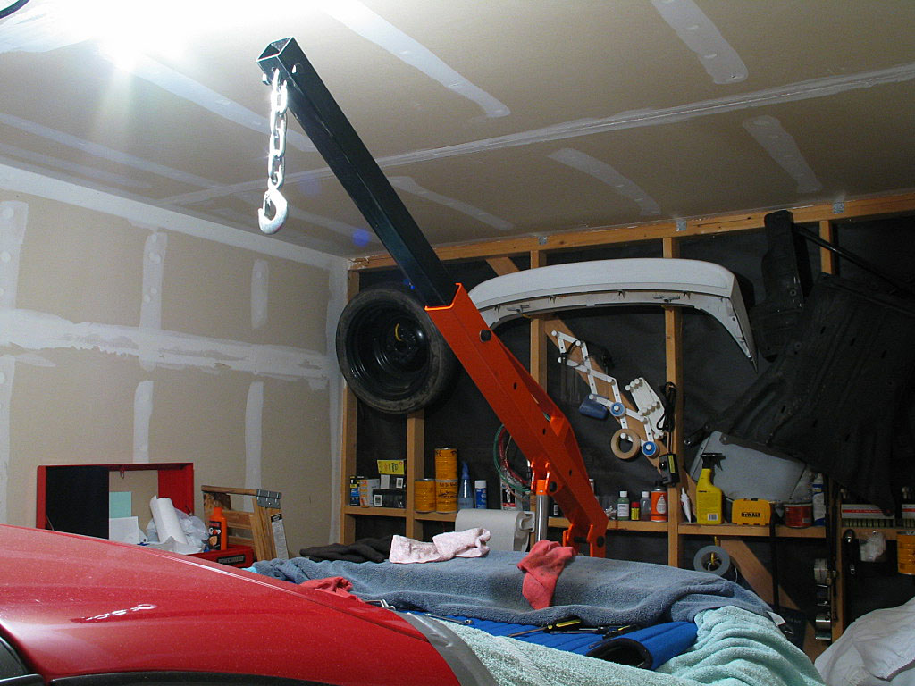
Remember, you'll be lowering the motor about 24", so take some measurements and make sure you have enough clearance where the boom is closest to the car body. If you have your hoist positioned in the rear, like the photo above, make sure you can lower the hook at least 24" before the boom hits the rear spoiler.
If you fail to measure this now, you might find that you need to raise the motor back up, secure it to the car, and add some length of chain. That's a lot of work that can be avoided by checking now ("Measure twice, cut once").
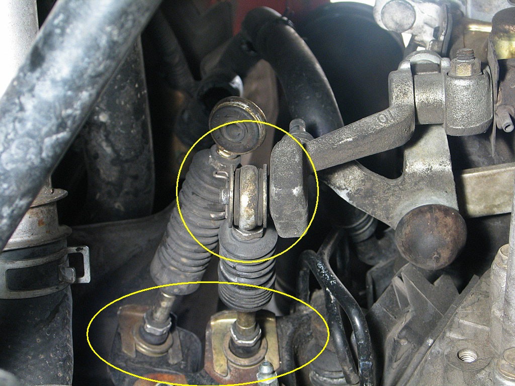
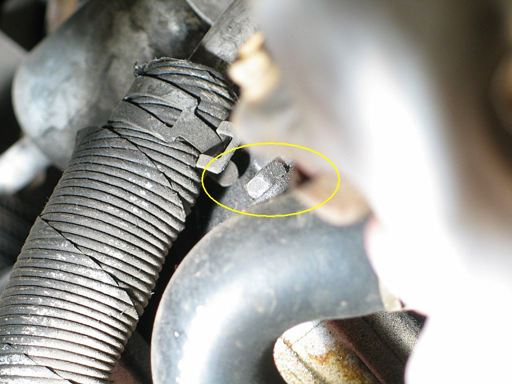
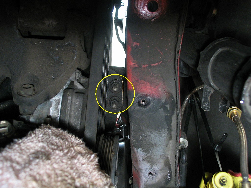
There are two "U" clips that retain the shifter cables to the support bracket, as seen in the yellow oval above. Pry these clips off, separate the cables from the bracket, and move them out of the way of the transaxle.
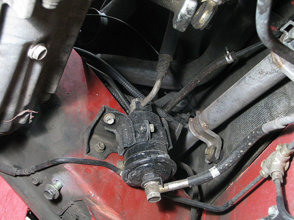
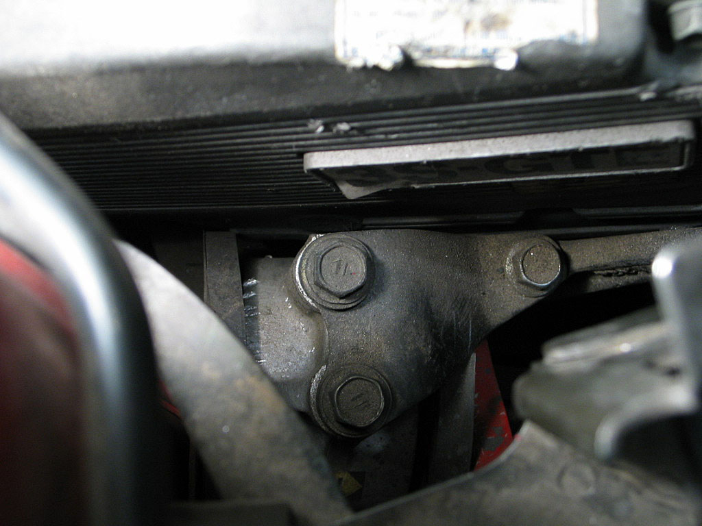
There's a 17mm thru-bolt that attaches the mounting bracket to the motor via a rubber isolator:
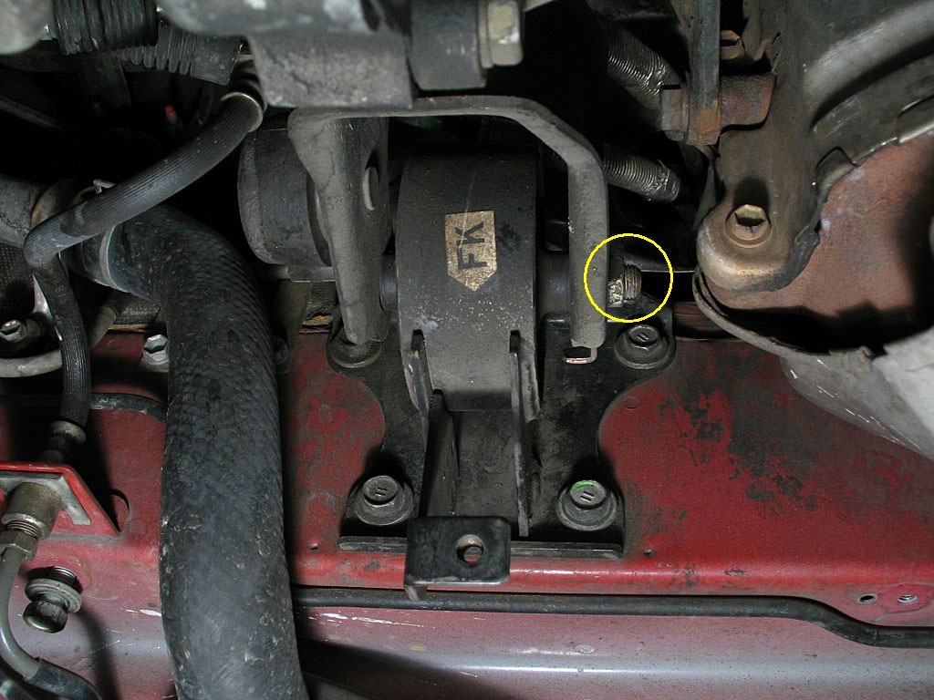
Just crack loose the nut on the thru-bolt for now.
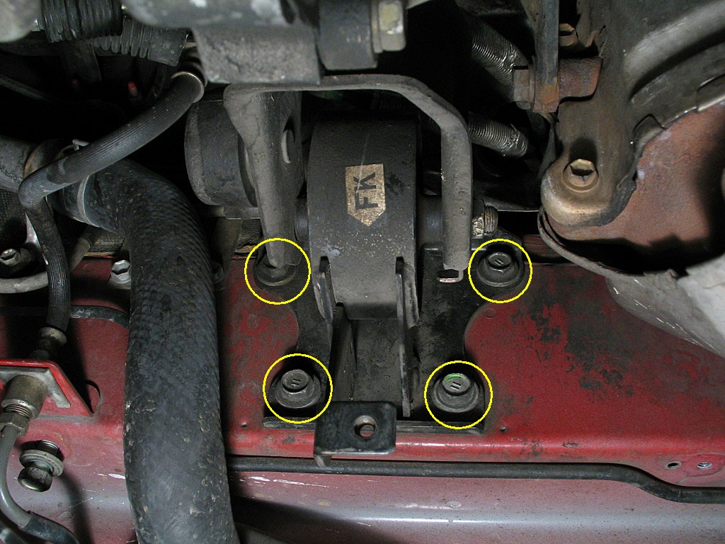
Crack all four of these bolts loose.
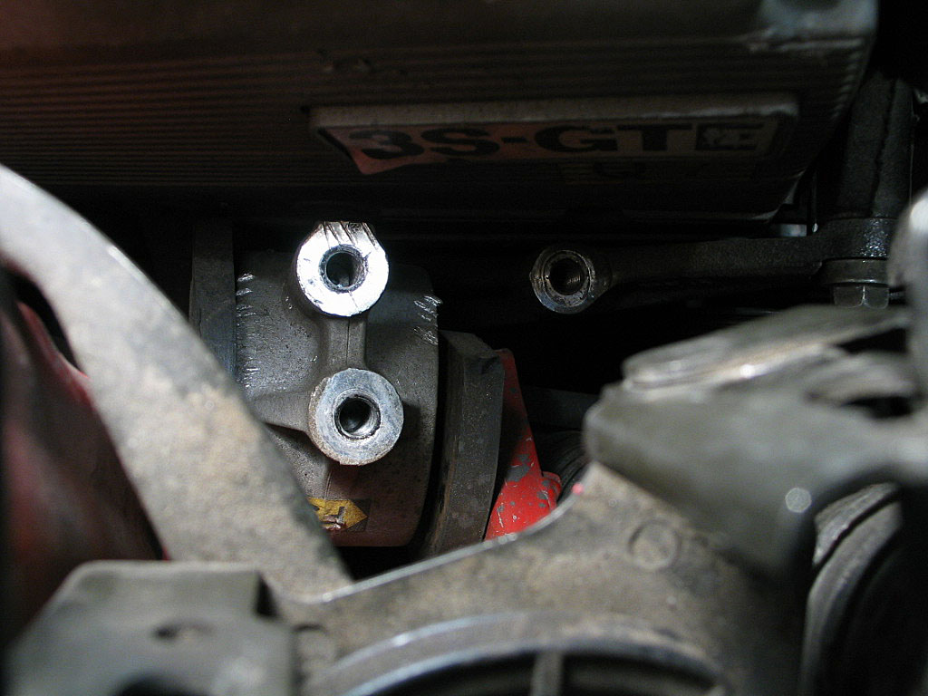
Remove the large thru-bolt, then remove the 14mm bolts and slide the mount off the transaxle bracket. You may find that rocking the motor a bit helps to free the thru-bolt.
Remove them both and remove the bracket.
At this point, the only attachment points for the motor and trans should be the right and left motor mounts. Take a moment now to verify that all brackets, hoses, and cables that attach to the motor have been disconnected.
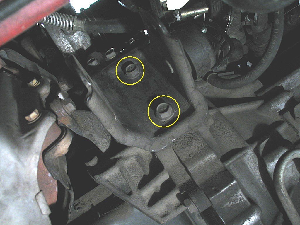
Remove these three bolts, as well as the mounting plate:
When removing these final bolts, NEVER place your hands or any part of your body in danger. Remember, when you remove a bolt with the weight of the motor on it, it's likely that the motor will lurch in one direction or another. Make sure you don't rest any part of your anatomy where it could be crushed.
On the left side of the motor, there's a 17mm thru-bolt that runs through a rubber isolator. This mount supports the left side of the motor/transaxle.
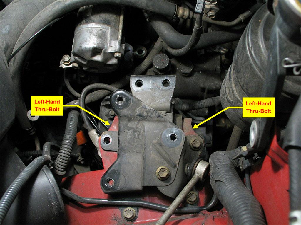
The bolt is not visible when viewed from directly above, but it's reasonably accessible.
Remove the nut, and carefully remove the bolt. You will probably find that there is still weight on it from the transaxle. It's difficult to get the hoist balanced exactly on the motor/trans assembly. However, by carefully adjusting the load on the hoist and by rocking the motor slightly, you should be able to remove the bolt.
Remove these two nuts.
The motor can now be lowered onto a dolly. You might need to rock it a bit to slide it off the right-hand mounting studs.