|
Last Updated
06 November, 2004
|
|
|
Back to Start Page
 1
2 3 4 5
6
7
1
2 3 4 5
6
7
 |
|
|
Removing the 3SGTE (continued)
|
|
| |
|
|
| |
With the fuse box out of the way, you have
access to a bracket that mounts the igniter, coil, and a condenser for the
radio. There are two 10mm bolts securing the assembly to the rear
firewall.
You'll need to remove the bolt closest to the left side of the car:
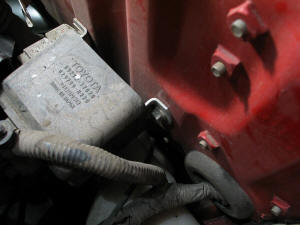
The other bolt only needs to be loosened a few turns:
You can remove the plastic cover if necessary to access the bolts, but
it's not required. Rotate the unit up from the left side and it should
slide out from the remaining bolt.
I removed the coil wire to protect it from damage, then I used a long
cable tie to secure the assembly to the motor.
|
|
| |
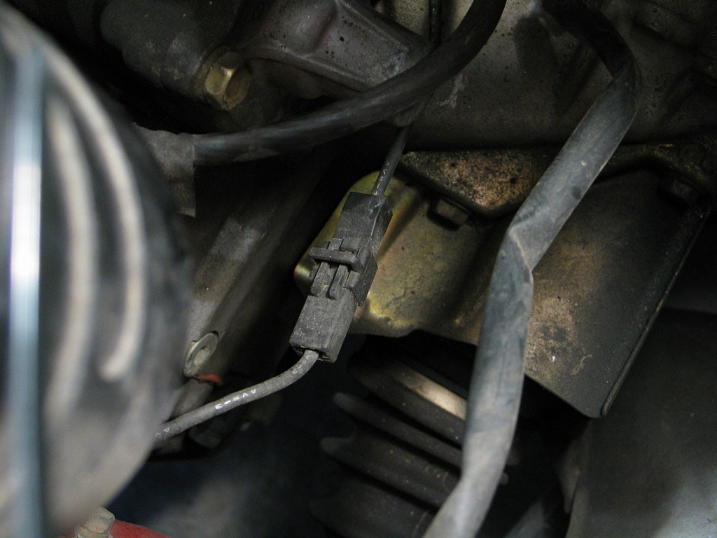
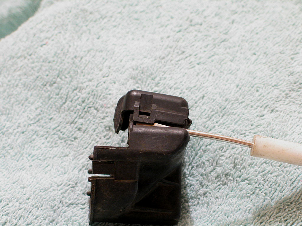
If you look down into the engine bay, you should see a ground wire connector:
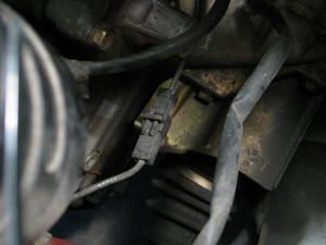
Separate the connector by pressing in on the locking tab and pulling it apart.
|
|
| |
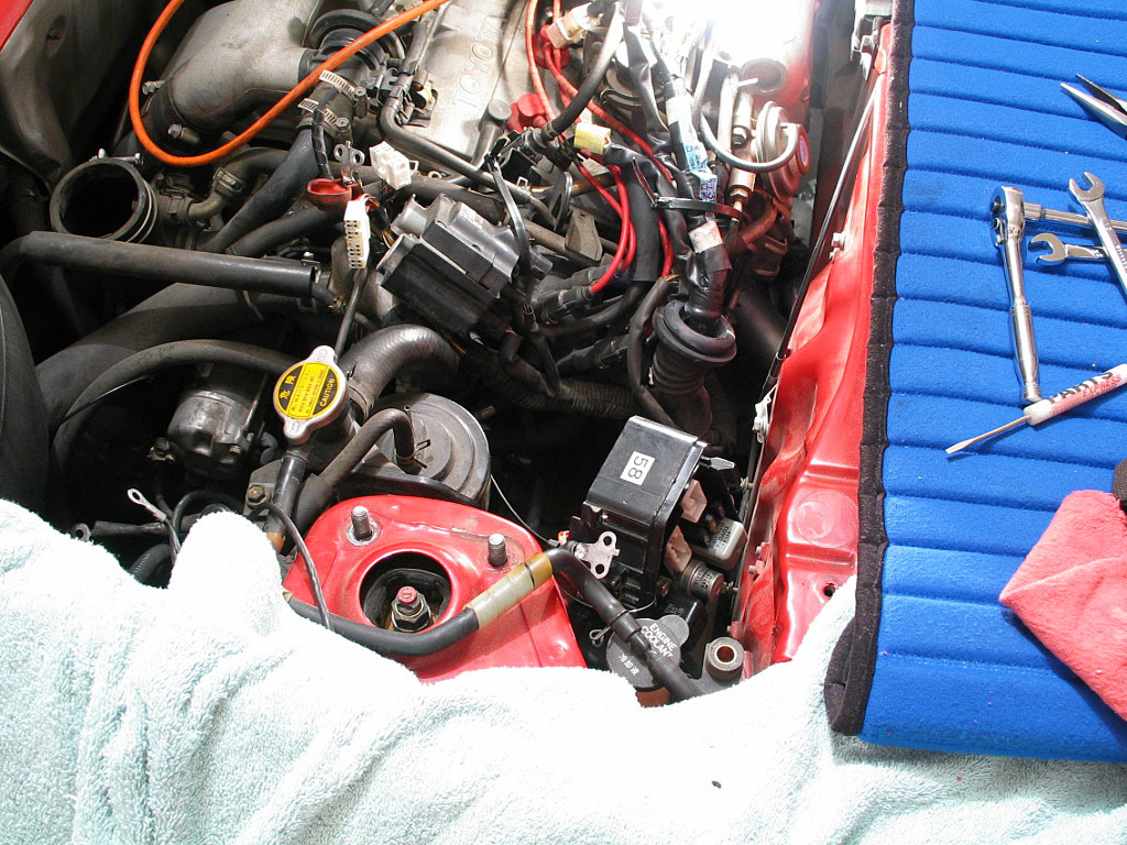
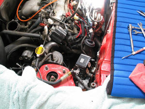
The engine bay is opening up now:
|
|
| |
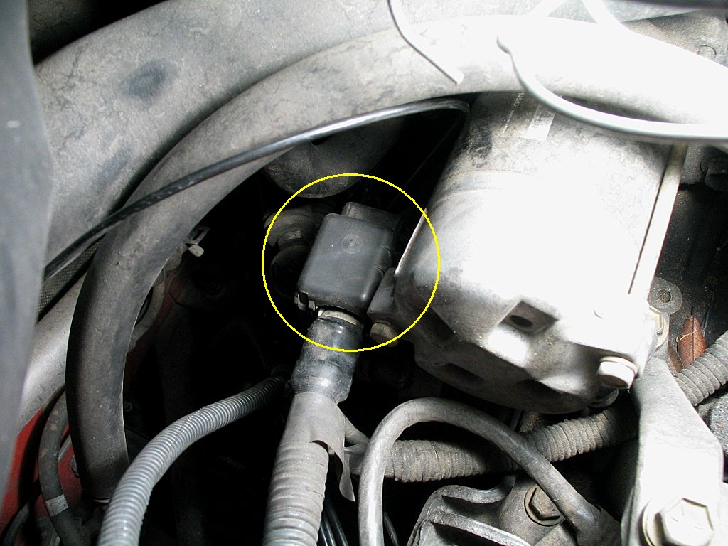
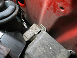
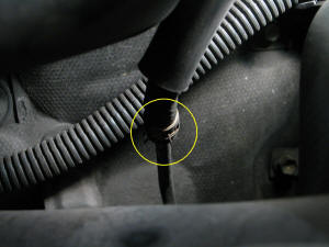
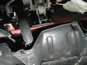
Towards the forward firewall, down by the
transaxle, is the starter. The starter cable connection is protected by a
plastic cover:
|
|
| |
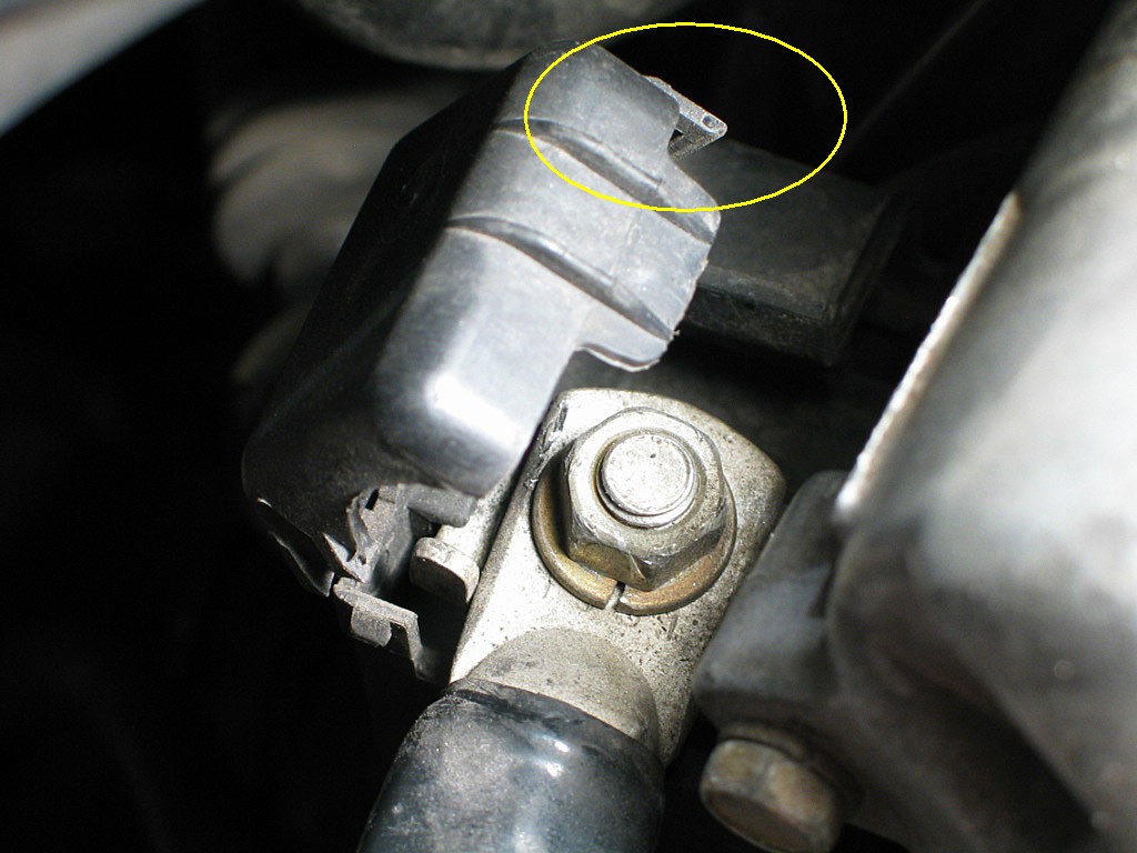
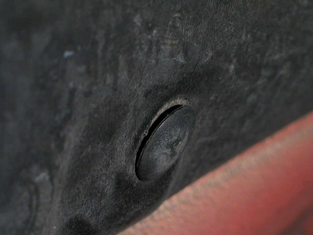
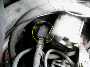
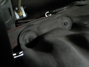
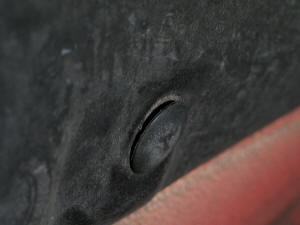
If you don't want to destroy the cover, you'll need to release the
locking tab on the "lid". The tab is totally obscured, on the inside of
the cover, and it needs to be pried out away from the housing to
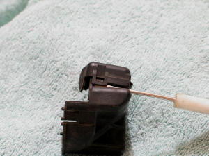
release. Here's a close up of the cover, with the tab just visible in
the yellow circle:

I managed to get a small flat-blade screwdriver under the tab and pried
it loose.
|
|
| |
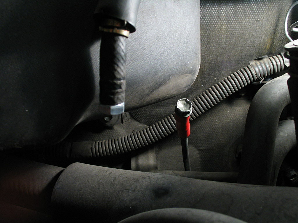
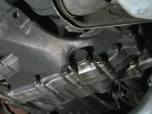
Once the top of the cover has been opened, remove the 12mm nut on the stud. In
my case, the nut was overtightened, and the assembly started to bend as I tried
to loosen the nut, so be careful.
|
|
| |
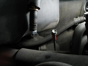
Nearby is the main ground cable:

Remove the 12mm bolt and secure the cable to the motor so it doesn't catch on
anything during the engine drop.
|
|
| |
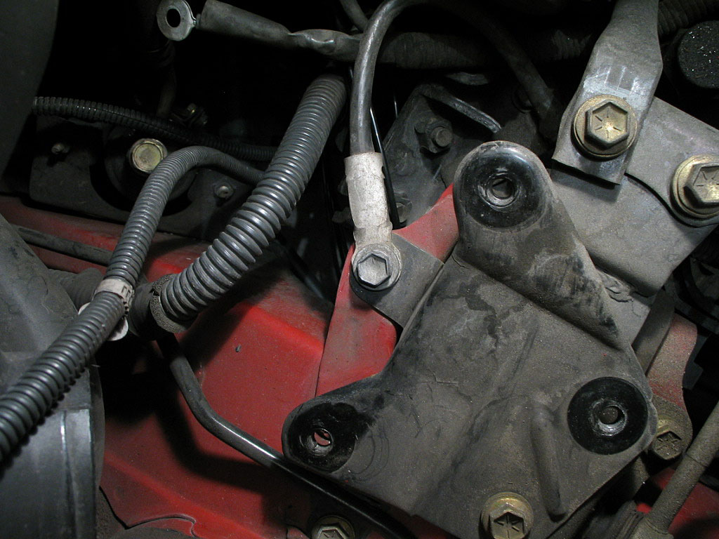
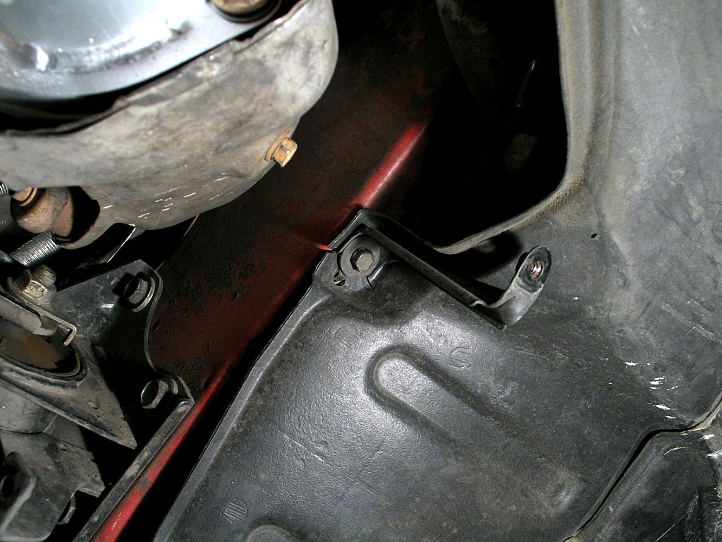
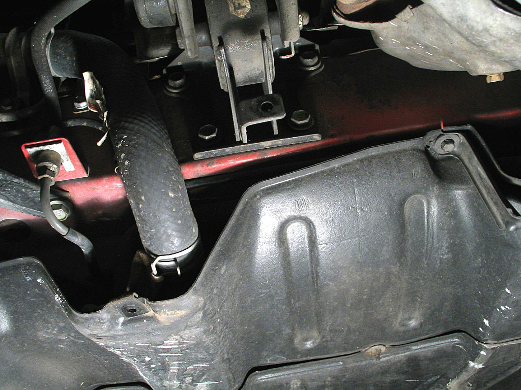
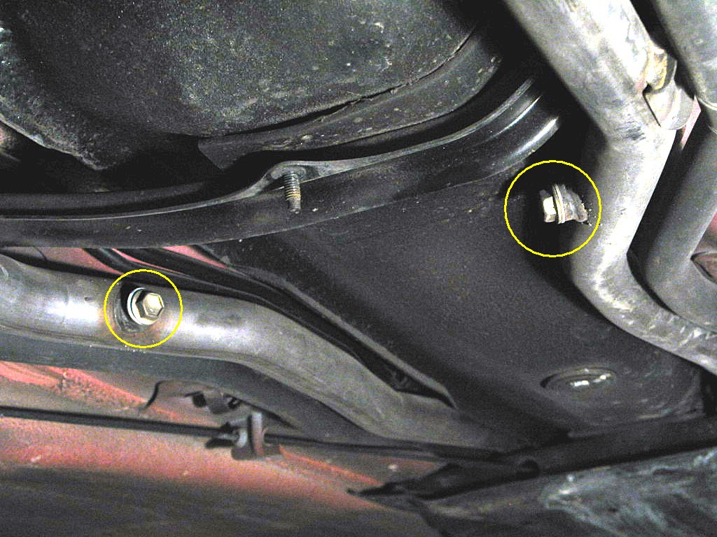
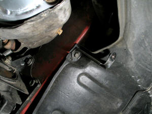
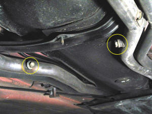
There are two engine support brackets very close to the ground strap. The engine
mounting stay is an angled tube that connects the left hand engine isolator to
the transaxle case. The lateral control rod mounts between the isolator and the
body, as shown below:
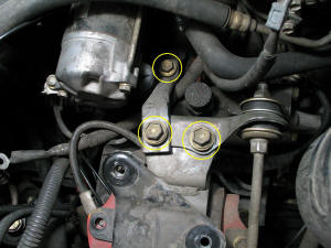
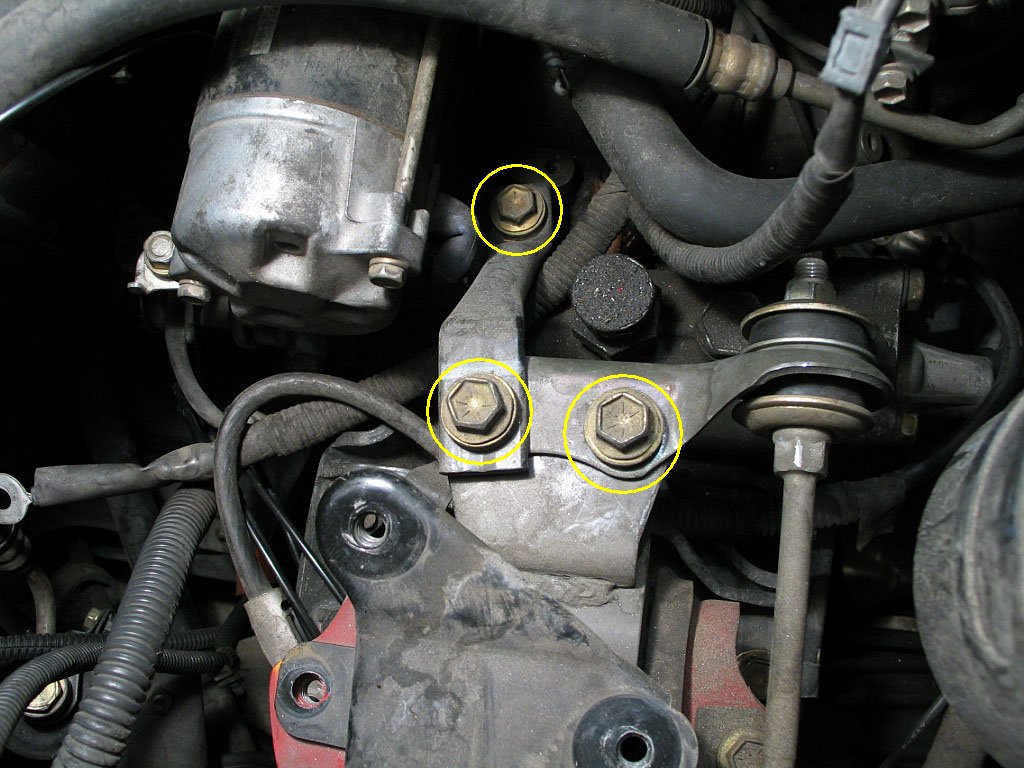
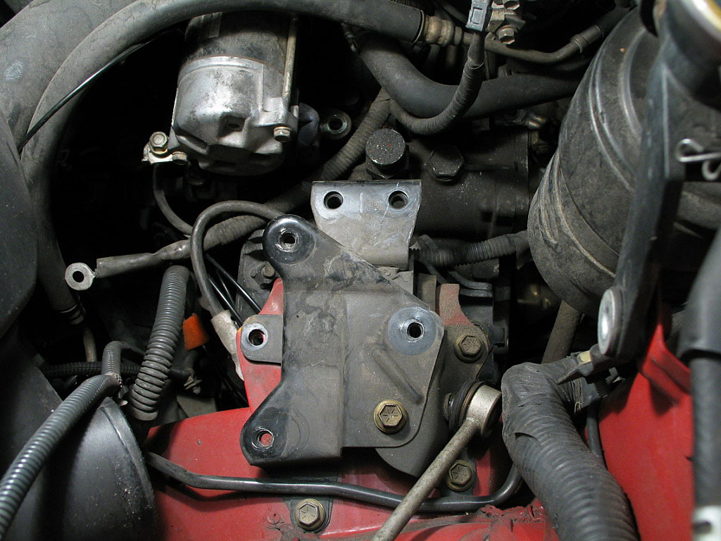
Remove all three bolts. Remove the engine mounting stay and set it aside. You
only have to remove the one bolt on the lateral control rod, and you can rotate
it up out of the way:

|
|
| |
Up near the forward firewall is the fuel return line. There is a hose clamp that
you need to loosen:
Slide the hose off the steel line.
I recommend plugging both sides of the line. I just used a bolt to plug the hose. On
the steel line, I used a short section of hose with a bolt plugging the end:
Plugging the line keeps any gasoline and fumes contained within the fuel system,
especially important when working in a garage.
|
|
| |
Reach into the cabin and move the heater temperature lever to the full HOT
position. This opens the heater core valve.
Loosen the coolant filler cap all the way, and just leave it sitting loosely on
the filler neck:
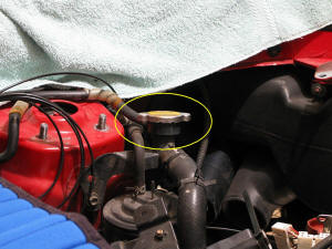
If you only loosen it a little, the vacuum created in the system when you open
the drain plugs will pull the cap back onto the neck and prevent proper
drainage.
|
|
| |
Crack loose the lug nuts on the rear wheels. Jack up the car high enough to
enable you to get all the way under it. Support it on four jack stands so that
it is relatively level. Not only is this safer, but the cooling system will
probably not
drain properly if only the rear of the car is raised.
|
|
| |
Remove the rear wheels. You'll need to remove them eventually, and
getting them out of the way now gains you easier access to the underside
of the car.
|
|
| |
Drain the engine oil. While this is not absolutely necessary, it certainly is
recommended. You'll need a 14mm box wrench or socket to loosen the drain plug.
|
|
| |
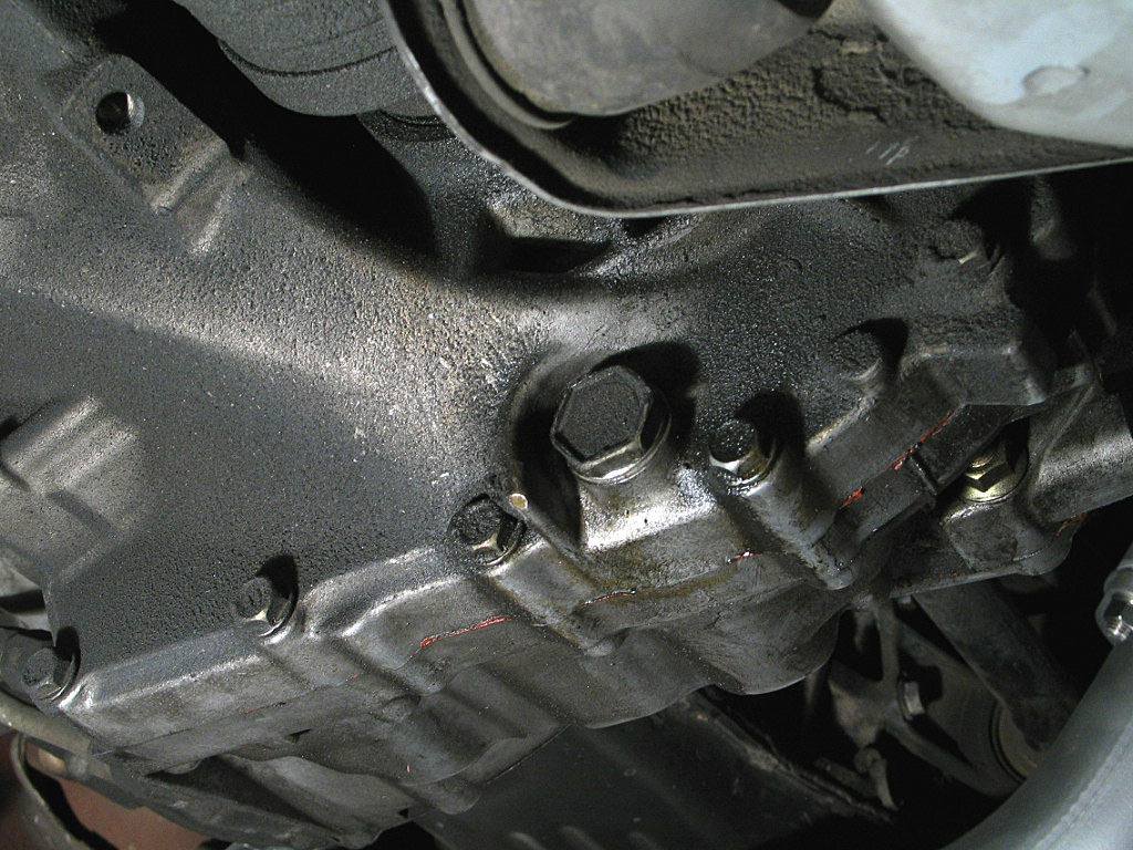
Drain the transaxle. You'll need a 24mm box wrench or socket to loosen
the drain plug:
|
|
| |
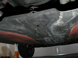
There are several plastic splash pans under the central tunnel, and you'll
remove three of them, working forward from the rearmost one. Toyota calls the
two rear pans "Engine Under Covers", although they don't actually reach
under the engine. The rearmost pan is attached with four 10mm
machine screws and one 10mm sheet metal screw:

Remove the bolts/screw and the cover.
|
|
| |
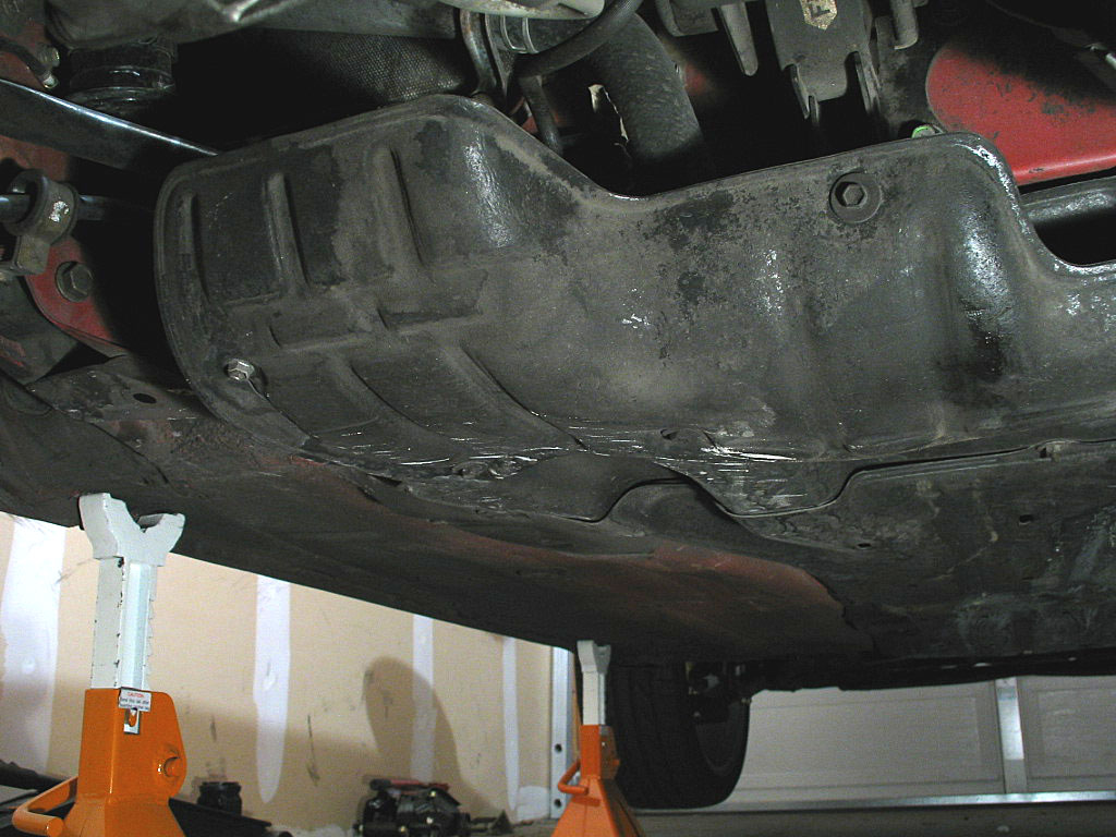
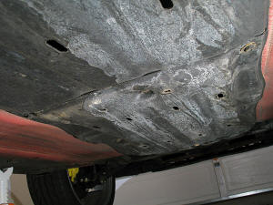
The next pan is also called an "Engine Under Cover". It's attached with
six 10mm bolts and a 10mm nut.
Remove this cover, and the small support bracket as well.
|
|
| |
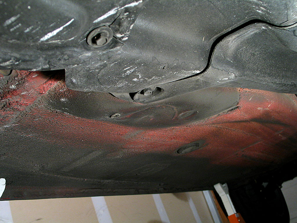
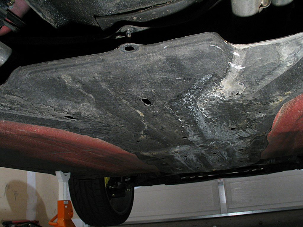
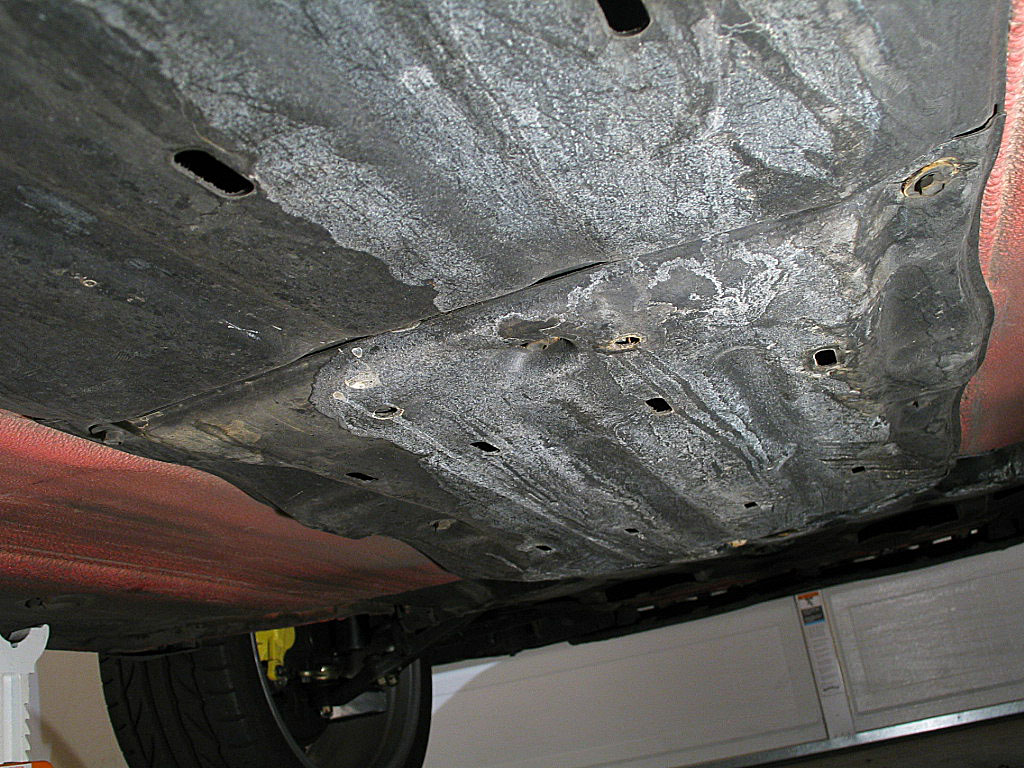
The next two pans are referred to as "Fuel Tank Protectors". The
rearmost one is attached with three 10mm bolts, and two plastic clips.
I guess it might be theoretically possible to remove the plastic clips
undamaged:
I tried prying one out and the head snapped off. I did manage to unscrew
the other one, but it was pretty beat up. Another mysterious engineering
choice by Toyota. These clips snap into captured nuts, so a standard
bolt would certainly work as well or better.
|
|
| |
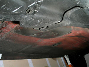
With the cover off, you can now access two coolant pipe drains:
Position a drain pan with a capacity of several gallons under one of the drain plugs. Loosen
it with a 12mm box wrench or socket. Be careful as the coolant will
shoot out quite a ways before the pressure drops.
Once the flow has slowed to a trickle, remove the other drain. Leave the
drain pan in position, as more fluid will drain as you remove
the hoses.
|
|
| |
Continued on next page... |
|
|
|
|
|
Back to Start Page
1
2 3 4 5
6
7
|
|
|
|
|